4 How to Use
4-6. Connection between devices
- 22 -
4-6. Connection between devices
4-6-1. Connection of power supply
The power supply specification of the alarm system is 100 to 120 VAC or 200 to 240 VAC, 50/60 Hz.
Prepare a power supply that complies with the specification.
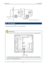
Before supplying power, connect the earth terminal of the alarm system to your grounding terminal. The
grounding resistance must be D type (below 100
Ω
). After the alarm system is grounded and it is in a safe
state, connect the power supply and other cables.
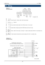
4-6-2. Connection to contact output
The indicator unit outputs the individual alarm contact 1 (gas alarm contact) and individual alarm contact 2
(gas alarm contact or fault alarm contact). Also, the base unit outputs the common alarm contact and
external buzzer contact.
The contact capacity is 250 VAC, 2 A for the common alarm contact and 250 VAC, 1A for the external
buzzer contact. (Both are resistance loads.) Configure an auxiliary relay circuit to connect a load over the
contact capacities.
4-6-3. Connection to 0/6/12 VDC output
The indicator unit and base unit output a signal of 0/6/12 VDC as standard.
A load current is 10 mA or less. (The external output signal of the indicator unit can be changed to the 4-20
mA output as an option.)
Use a shielded cable equivalent to CVVS for connection.


