4 How to Use
4-6. How to wire
- 19 -
NOTE
The following table shows an example of overall outer diameters of cables. Use them for reference.
The overall outer diameters must be checked because they somewhat vary between manufacturers.
Number of core
CVV 1.25 mm
2
(AWG16)
CVV 2 mm
2
(AWG14)
CVVS 1.25 mm
2
(AWG16)
CVVS 2 mm
2
(AWG14)
2
Φ
9.5
Φ
10.5
Φ
10.0
Φ
11.0
3
Φ
10.0
Φ
11.0
Φ
10.5
Φ
11.5
4
Φ
10.5
Φ
11.5
Φ
11.0
Φ
12.0
5
Φ
11.5
Φ
12.5
Φ
12.0
Φ
13.0
6
Φ
12.5
Φ
13.5
Φ
13.0
Φ
14.0
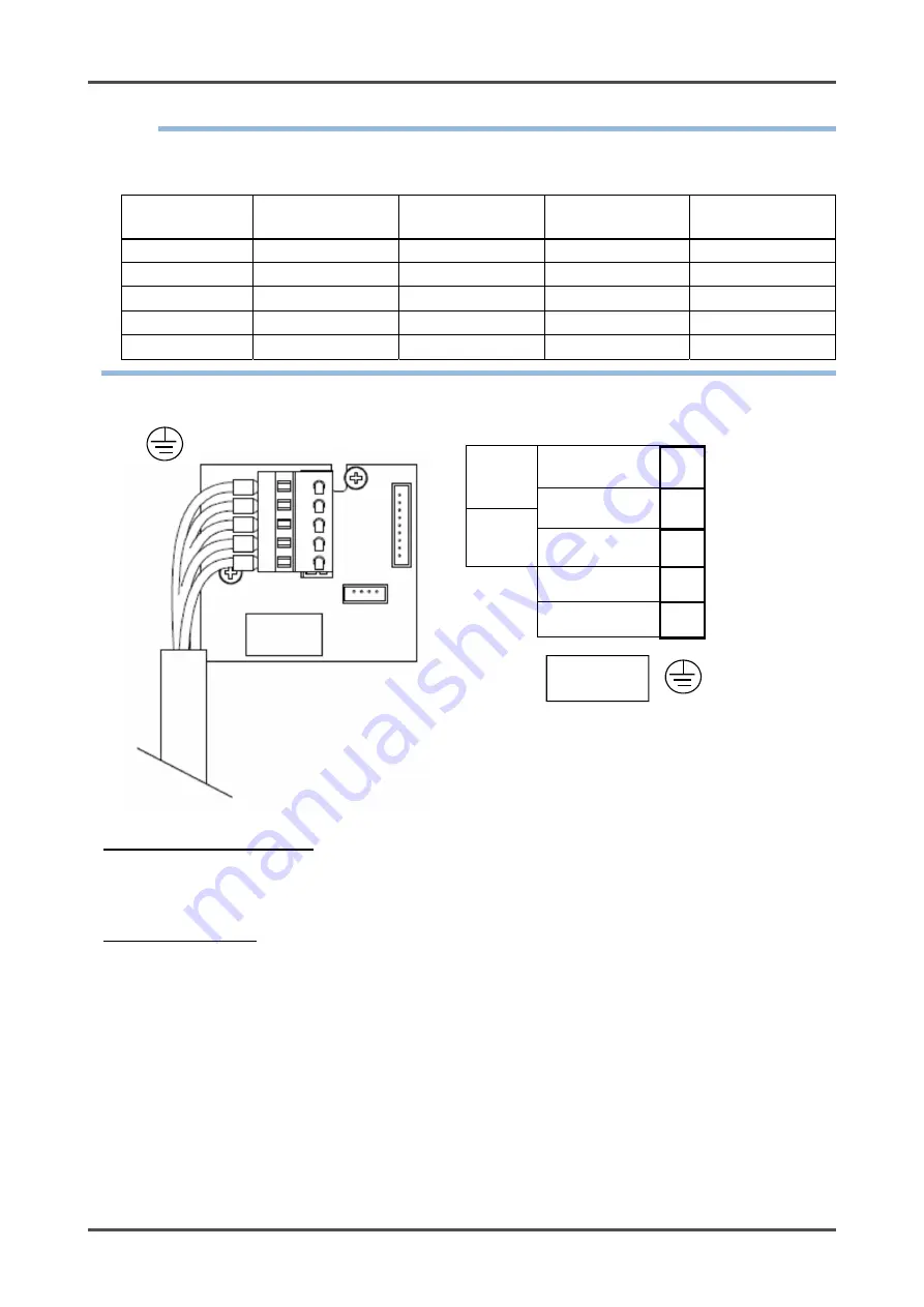
<Figure of Terminal Plate>
24 VDC
DC+ 1
- (Common)
2
4 - 20
mA
Sig+ 3
Contact 4
Contact 5
<Specifications of Terminal Plate>
Specifications of terminal plate
Rated voltage: 250 VAC
Rated current: 12 A
However, it depends on cables to be used.
Connection conditions
Cables: 0.25 - 2.5 mm
2
Bare wire length: 8 - 9 mm
Connecting tool: Dedicated handling lever (accessory) or driver (edge 3.5 x 0.5 mm)
<When 4-20mA output is not used>
This detector has a self-diagnosis function which shows E-9 on LED display when 4-20mA is not properly
outputted.
If 4-20mA output is not necessary, connect the following fixed resistance (lead type) to the terminal 2 and 3
(”Sig+” and “-(common)”).
Resistance value : 100-300
Ω
Rated power : 0.25W or more
Insert a cable and the above resistance together into Terminal 2 (common), and insert lead part of the
resistance into terminal 3 (Sig+). After that, check the immovability.
Grounding
terminal


