background image

4 How to Use


4-3. Precautions for system designing 


- 17 - 

SD-1DGH-AS 


 CAUTION 

An unstable power supply and noise may cause malfunctions or false alarms. 
The descriptions in this section must be reflected on the designing of a system using the detector. 


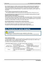
Do not install the detector in a place exposed to direct sunlight or sudden changes in the temperature. 

When selecting installation points, avoid a place where it is exposed to direct sunlight or radiant heat 
(infrared rays emitted from a high-temperature object), and where the temperature changes suddenly. 
Condensation may be formed inside the detector, or the detector cannot adjust to sudden changes in the 
temperature. 
 

Keep the detector (and its cables) away from noise source devices. 

When selecting installation points, avoid a place where high-frequency/high-voltage devices exist. 


Do not install the detector in a place where maintenance of the detector cannot be performed or where 
handling the detector involves dangers. 

Regular maintenance of the detector must be performed. 
Do not install the detector in a place where the machinery must be stopped when maintenance is performed 
in its inside, where parts of the machinery must be removed to perform maintenance, or where the detector 
cannot be removed because tubes or racks prevent access to it. Do not install the detector in a place where 
maintenance involves dangers, for example, near a high-voltage cable. 
 

Do not install the detector in machinery which is not properly grounded. 

Before installing the detector in machinery, the machinery must be grounded properly. 
 

Do not install the detector in a place where interference gases exist around it. 

The detector must not be installed in a place where interference gases exist around it. 


4-3. Precautions for system designing 


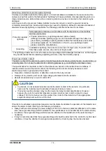
Using a stable power supply 

The external output and alarm contact of the detector may be activated when the power is turned on, when 
momentary blackout occurs, or while the system is being stabilized. In such cases, use a UPS, or take 
appropriate actions on the receiving side of output signals. 
The detector must be provided with the following power supply. 
 

Power supply voltage  24 VDC (17 – 26.4 VDC): Terminal voltage of the detector 

Allowed time of 

momentary blackout 

Up to 10 milliseconds 
(To recover from the momentary 
blackout for 10 milliseconds or more, 
restart the detector.) 

Example of actions 
To ensure continuous operation and 
activation, install a UPS outside the 
detector. 

Others 

Do not use it with a power supply of 
large power load or high-frequency 
noise. 

Example of actions 
Use a line filter to avoid the noise source 
if necessary. 


Summary of Contents for PT2-169

Page 1: ...PT2E 2525 Smart Transmitter Gas Detector Head SD 1DGH AS Operating Manual PT2E 170 PT2 170...

Page 2: ...4 6 How to tube 26 5 How to Operate 27 5 1 Preparation for start up 27 5 2 Basic operating procedures 28 5 3 How to start the detector 29 5 4 Modes 31 5 5 User mode 32 5 6 Flow Rate Adjustment 35 5 7...

Page 3: ...0 to 2000ppm as examples such as examples of LED display 1 2 Purpose of use This detector is a fixed type gas detector head that detects leak of combustible toxic gases and performs the alarm activati...

Page 4: ......

Page 5: ...d by RIKEN KEIKI Do not apply a strong force or shock to the window plate The explosion proof performances may be deteriorated due to damages The explosion protection conditions for the detector is lo...

Page 6: ...rol circuit securely connect it to a protective grounding circuit Tubing The detector is designed to draw gases around it under the atmospheric pressure Be sure that excessive pressure is not applied...

Page 7: ...y monitor the temperature humidity of the sampling point to prevent condensation inside the tube In particular when detecting a gas which is dissolved into water and corrodes contacted materials such...

Page 8: ......

Page 9: ......

Page 10: ......

Page 11: ...ave a gas detector head SD 1DGH incorporated in the sampling device The internal tubing required for SD 1DGH has been arranged prior to shipment CAUTION Use the supplied dedicated control key to opera...

Page 12: ......

Page 13: ...sed to switch menus or change a value DOWN 5 Power lamp Power lamp Detection mode It lights up in green Maintenance mode It blinks in green 6 Alarm lamp Alarm lamp It lights up in red when the alarm s...

Page 14: ...alarm contact ALARM or 2 Fault contact FAULT or 3 Select either gas alarm or contact ALARM FAULT Contact activation De energized De energized at a normal state ON ALARM Closed contact at an alarm sta...

Page 15: ......

Page 16: ...time users but also the users who have already used the product must follow the operating precautions Ignoring the precautions may damage the detector resulting in inaccurate gas detection 4 2 Precau...

Page 17: ...ntenance or where the detector cannot be removed because tubes or racks prevent access to it Do not install the detector in a place where maintenance involves dangers for example near a high voltage c...

Page 18: ...ormation on how to use a lightning arrester please contact the manufacturer Grounding In addition to lightning there are more sources of surge noise To protect units from these noise sources the units...

Page 19: ......

Page 20: ......

Page 21: ...nduit must be connected to a grounding circuit When stranded wires are used prevent wires from contacting each other Use the dedicated handling lever to wire Use appropriate cables to wire 4 5 How to...

Page 22: ......

Page 23: ......

Page 24: ......

Page 25: ...grounding wire use cable lugs to safely connect it to a grounding terminal without looseness or twist Use ring terminals to connect the grounding terminal with the ground and use the grounding wire w...

Page 26: ...under the atmospheric pressure Be sure that excessive pressure is not applied to the sampling inlet and outlet GAS IN GAS OUT of the detector Detected gases must be exhausted from the detected gas ex...

Page 27: ...nnected to external device properly Check that the power supply voltage is compliant with the specifications Because the external contact may be activated during the adjustment take measures to preven...

Page 28: ......

Page 29: ......

Page 30: ...plied The required warm up powered time depends on the unpowered time for the sensor The time shown in the table shown below must be met Unpowered time Guidelines for warm up powered time 24 hours or...

Page 31: ...ment 2 1 Perform the zero adjustment Span Adjustment 2 2 Perform the span adjustment Zero Span Initialization 2 3 Initialize zero span values Environmental Setting 2 4 Used for various environmental s...

Page 32: ......

Page 33: ......

Page 34: ......

Page 35: ......

Page 36: ...ncentration Display In case of over the detection range Over Scale is displayed on the LED Power Indicator Lamp POWER Green During operation this lights up continuously Alarm Indicator Lamp ALM Red It...

Page 37: ...main valve of the gas and then check that the gas concentration reading dropped Access the gas leak point equipped with a protective gear to avoid dangers caused by possibly remaining gases and check...

Page 38: ......

Page 39: ...reading Therefore the reading might be fluctuated around zero even in a normal environment This function obscures influences by environmental changes and interference gases around zero that have no m...

Page 40: ...aintain the performance as a safety unit Maintenance item Maintenance content Daily maintenance Monthly maintenance Regular maintenance Power Supply Check Check that the power lamp lights up Concentra...

Page 41: ...bnormalities Checks the flow rate by using an external flow meter to verify the correctness of the flow rate indicator on the detector If the flow rate is incorrect performs the flow rate adjustment F...

Page 42: ...ize zero span values Environmental Setting 2 4 Used for various environmental settings 2 4 0 Sensor Power Supply ON OFF 2 4 1 INHIBIT Setting 2 4 2 Alarm Setpoint Setting 2 4 3 Alarm Delay Time Settin...

Page 43: ......

Page 44: ...ous Electrical Settings Display Display various electrical settings This is not used by the user 2 6 Enter the factory mode This is not used by the user 2 7 Return to the user mode rET is displayed Pr...

Page 45: ......

Page 46: ......

Page 47: ......

Page 48: ......

Page 49: ......

Page 50: ......

Page 51: ......

Page 52: ......

Page 53: ......

Page 54: ...s Replacement intervals Quantity pieces per unit Remarks 1 Guard assembly 6 months 3 8 years 1 2 Aspirator cap 6 months 3 8 years 1 The operation must be checked after replacement by a qualified servi...

Page 55: ...der the following environmental conditions In a dark place under the normal temperature and humidity away from direct sunlight In a place where gases solvents or vapors are not present 8 2 Procedures...

Page 56: ...y system Provide the rated voltage Take measures such as checking or adding the UPS power supply line filter and insulation transformer Cable abnormalities open circuit not connected short circuit Che...

Page 57: ...cannot be eliminated completely For information on actions such as removal filter please contact RIKEN KEIKI Disturbance by noise Turn off and restart the detector If such a symptom is observed frequ...

Page 58: ...ed Gas alarm pattern Auto reset Fault alarm self diagnosis System abnormalities sensor abnormalities Fault alarm display FAULT lamp on yellow detail display Fault alarm pattern Auto reset Alarm contac...

Page 59: ...s 59 SD 1DGH AS External dimensions Approx 400 W x265 H x102 D mm Weight Approx 5 6 kg Outer color Munsell 7 5BG5 2 When a half union for gas IN side is changed check also the external filter IN OUT d...

Page 60: ...10 Product Specifications 10 1 List of specifications SD 1DGH AS 60 Adapter A NPT1 2 Adapter B NPT3 4...

Page 61: ...ormalities Fault alarm display FAULT lamp on yellow detail display Fault alarm pattern Auto reset Alarm contact No voltage contact 1a de energized energized in response to an alarm or energized de ene...

Page 62: ...10 Product Specifications 10 1 List of specifications SD 1DGH AS 62 Outline Drawings...

Page 63: ...Detection principle Semiconductor Type Metal dioxide can measure gas concentration based on changes in the electric conductivity of semiconductor caused by gas adsorbed on its surface RL Load resista...

Page 64: ...of the detection range ppm A concentration unit that means part per million of the combustible gas to be detected Calibration Adjusts the readings to the calibration gas concentration value by using t...

Page 65: ......
Reviews: