3 Product Components
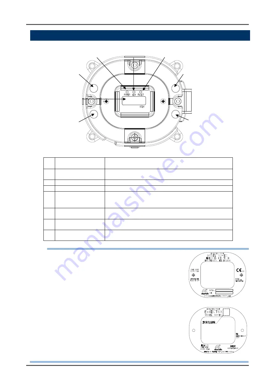
3-2. Names
and functions for each part
- 9 -
3-2. Names and functions for each part
(1)
MENU/ESC key
Used to enter the maintenance mode.
It is also used to cancel in a specific mode.
(2)
SET key
It is used for value confirmation and so on in a specific
mode.
(3)
▲ key
Used to switch menus or change a value (UP).
(4)
▼ key
Used to switch menus or change a value (DOWN).
(5)
Power lamp
Power lamp.
Detection mode: It lights up in green.
Maintenance mode: It blinks in green.
(6)
Alarm lamp
Alarm lamp. It lights up in red when the alarm setpoint value
is reached.
(7)
Fault lamp
Fault lamp. It lights up in yellow when an abnormality is
detected in the detector.
(8)
Concentration value
display
Display the gas concentration and so on.
NOTE
The nameplate on the front side of the detector (see the figure on the
right) shows the precautions to be taken for explosion-proof
performances. Read these precautions as well as "2. Important
Notices on Safety."
The detector manufactured in accordance with ATEX/IECEx
specifications has a nameplate on the front side that shows also the
serial number, date of manufacture etc.
INST.No.: Serial number
DATE : Date of manufacture
(8) Concentration value display
(5) Power lamp
(6) Alarm lamp
(7) Fault lamp
(1) MENU/ESC key
(2) SET key
(4) ▼ key
(3) ▲ key
<ATEX/IECEx Specifications>
<TIIS Specifications>
Summary of Contents for PT2-177
Page 1: ...PT2E 1771 Smart Transmitter Gas Detector Head SD 1OX Operating Manual PT2E 177 PT2 177 ...
Page 3: ......
Page 56: ......


