background image


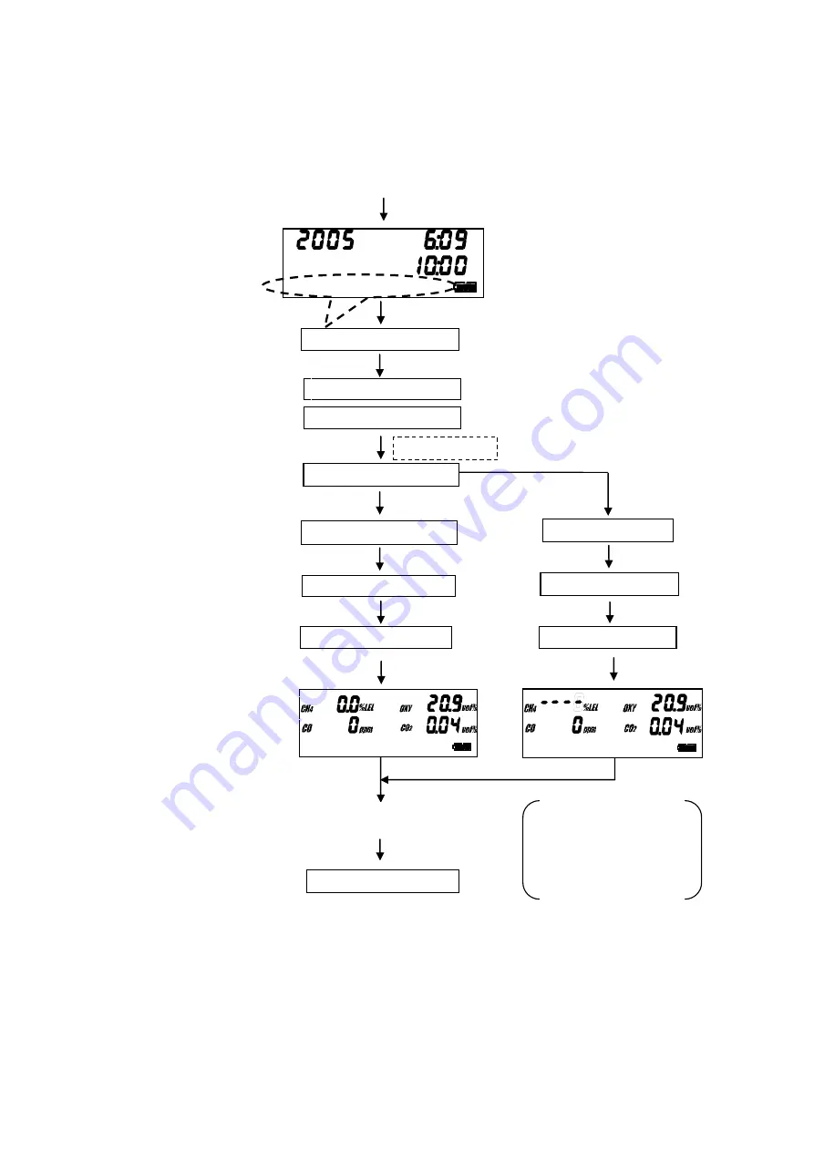
3-3.Start-up and end-up


  When press power switch for 3 sec, the power gets on and this shall start up through the voltage 
check, filter connection check and sensor connection check. 


Press power switch for 3 sec 

PROBE  OK? 

SENSOR  CHECK 

SENSOR  OK 

WARM  UP  30 

Accessory connection check 

(Display word atternately) 

FILTER  OK? 


【Sensor normal】 

Warm up 

Detection mode 

ENTER key   

FAIL SENSOR 

STAND  BY 

Detection ready 


Power off 

Press POWER SW for 3 sec 

GOOD - BYE 

PREPARATION 

Date/time display 


WARM  UP  30 

STAND  BY 

Trouble  sensor  shall 

show “……”. 

・Press ENTER key 

【Sensor trouble】 

Stand-by 

Summary of Contents for RX-515

Page 1: ...PT0E 1015 Portable Combination Gas Detector RX 515 Operating Manual MARINE USE...

Page 2: ...s content by experienced users as well as beginners The following headline shall be shown to carry out the safety and effective work in this instruction manual Model RX 515 is approved by certificate...

Page 3: ...lay Each function Setting mode Alarm setting Date time setting LCD back light Data logger Maintenance check Battery replacement Gas calibration Span adjustment Filter replacement Sensor replacement Da...

Page 4: ...t gas presence do it in short time and make sensor cleaning by sucking fresh air after measurement Caution Do not drop or damage it This is a fire instrument When strong shock is given the function ma...

Page 5: ...ure PEAK SW This is used when to let the peak displayed MODE ESC SW This is used when enter the set mode or cancel the input ALARM LAMP When trouble alarm triggers this shall blink and light out LCD w...

Page 6: ...5 Standard accessories Carrying case with shoulder strap Filter tube with flow monitor and junction tube Gas sampling probe Gas sampling hose CO2 scrubber Alkaline...

Page 7: ...ith plummet Gas sampling hose 30m with float type sampling head Gas sampling bag 1L for LEL and VOL and calibration gas cylinder Absorbent cotton Water proof filter for filter tube 10pcs Steel storage...

Page 8: ...k creek or twist on the instrument Preparation 1 Dry batteries are put into instrument 2 Put carrying case on to instrument 3 Connect the instrument Gas inlet Filter tube with flow monitor Sampling ho...

Page 9: ...ress power switch for 3 sec PROBE OK SENSOR CHECK SENSOR OK WARM UP 30 Accessory connection check Display word atternately FILTER OK Sensor normal Warm up Detection mode ENTER key FAIL SENSOR STAND BY...

Page 10: ...When calibrate zero point of CO2 it is required to remove CO2 in air by CO2 removal filter Float Caution When make zero adjustment proceed to do it after having fresh air sucked into instrument for o...

Page 11: ...TER key ADJ ZERO Go back to the operation display by ESC key ESC key ZERO sets OK ZERO SET OK Press for 5 sec and move to zero adj of CO2 When press ENTER key CH4 O2 CO zero cal starts Calibration Gas...

Page 12: ...Then it will be different by the airtight of CO2 scrubber storage temp and humidity The number in the list for one time per minute will be a hint of it but when CO2 in air can not be specified use it...

Page 13: ...ubber shut off the ventilation from atmosphere When the absorbent agent is mixed with air the absorption capability will be dropped by CO2 in air Keep the CO2 scrubber from the sun light and store in...

Page 14: ...e at pump work stop Do not block the pump outlet the reading shall show a little higher When measure oxygen in inert gas for a long time be sure to measure lower than 15 CO2 by all means When exeed hi...

Page 15: ...int and stop to operate temporarily the pump only stops operation When stop the pump operation the power consumption shall be reduced by about 40 Then the other than pump is on active and once the pum...

Page 16: ...s before use 2 Power OFF When hold and press power SW for about 5 sec the buzzer sounds 8 times and the power will be off HOLD KEY PUMP OFF HOLD KEY PUMP ON Press pump key for 3 sec Pump work will be...

Page 17: ...ed mode Alarm buzzer lamp WARNINNG 1st alarm Lamp ALARM OVER 2nd Over alarm Lamp Intermittent tone LED blinking Intermittent tone LED blinking Alarm 1st alarm set CH4 CO CO2 Alarm 1st alarm set O2 WAR...

Page 18: ...OFF After power off replace the battery with new one See it for 6 1 Battery replacement REPLACE BATT Low battery Power OFF operation available only by POWER key LOW FLOW Pump OFF ESC Pump ON Caution...

Page 19: ...troubled will be shown Sensor for trouble detected at start up time shall be shown Buzzer will sound continuously After showing FAIL SENSOR it does not accept other than Power off Power off available...

Page 20: ...m point will be changed to alarm set display To alarm setting PEAK key MODE key To alarm setting MODE key PEAK key Alarm setting PEAK key Date setting MODE key MODE key When hold and press PEAK key fo...

Page 21: ...shall be shown Then 2nd alarm point of CH4 shall be shown on the display When change by or key confirm it by ENTER key When press the setting by ESC key go back to 1st alarm point CH4 1st alarm point...

Page 22: ...ouble on Light on First set the year The set number shall blink The change of number is set by or key Press ENTER key and the number is entered When press ESC key the set work stops in the way and go...

Page 23: ...s deleted and shall record the latest data 3 Alarm event It is recorded as event that alarm triggers Alarm trigger time and measuring gas and kind of alarm AL1 AL2 OVER shall be recorded The record nu...

Page 24: ...es and put on new batteries by taking care of battery polarity Close the battery cover The following battery types are the only battery types that may be used 1 Duracell Ultra MN1400 2 Panasonic LR14...

Page 25: ...ed to it fax the span by pressing ENTER key After span adjusted proceed to the oxygen display Hold and pressing ZERO and PUMP key simittaneously in the operation mode First CH4 display shall be shown...

Page 26: ...ingredient in the lighter gas the sensor function may deteriorate Caution Do not supply the calibration gas by plugging in the inlet of canned gas directly It may lead to the internal damage of instr...

Page 27: ...ation 3 The reading is unstable When the sensor replacement is needed contact RIKEN KEIKI or nearest agent Daily check and regular check 1 Daily Is there any damage for switches lamps display and pane...

Page 28: ...low monitor internal parts accessories 3 months 0 5 6 Cotton Filter tube with flow monitor internal parts accessories 3 months 0 5 7 Packing Filter tube with flow monitor internal parts accessories 6...

Page 29: ...in the box kept in originally When the storage box was lost store it in vinyl pack etc Scrap of products When dispose the waste follow the regional low etc locally and do it in the same category wite...

Page 30: ...PAN CAL FAIL FAIL SPAN Cal gas is not supplied correctly Make gas calibration again by supplying cal gas See 6 2 GAS CALIBRATION Sensor trouble Make sensor replacement Power can not be ON No power on...

Page 31: ...e to the true valued PEAK value MAX or MIN value in a period ALARM preset value This is an alarm preset point value to give alarm when it comes to this alarm point Maintenance check This is a work to...

Page 32: ...seefa Alkaline batteries Size C only MED approved Power source Alkaline batteries Size C 4pcs Continuous Operation Alkaline battery Approx 30 hours no alarm or light at 25 Display Digital LCD with bac...

Page 33: ...nsitivity against CO etc which have the different absorption wave from the measuring gas Then there is no sensitivity against N2 and H2 etc which cannot absorb infrared As compared with the convention...

Page 34: ...lyzed current generated at that time The electrochemical sensor is designed to keep the interface between electrode and electrolyte at a constant potential Bias voltage and is the method to electrolyz...

Page 35: ......

Reviews: