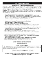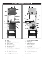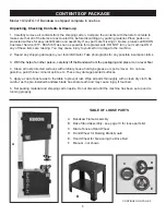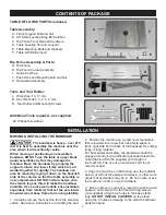
15
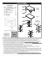
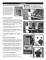
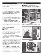
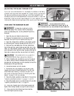
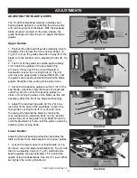
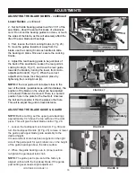
FIGURE 19
ADJUSTMENTS
ADJUSTING THE BLADE TENSION
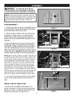
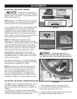
1. Always tension the blade with
the Quick Release Lever (#17C) in the “ON” position.
Failure to do so could result in lack of blade tension or
tension failure. Figure 16.
NOTE:
Release / turn ‘OFF’ the Tension Lever only to
change the blade, or to prolong the life of the blade
when the saw is not in use for extended periods.
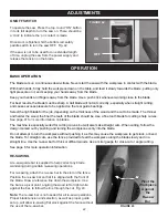
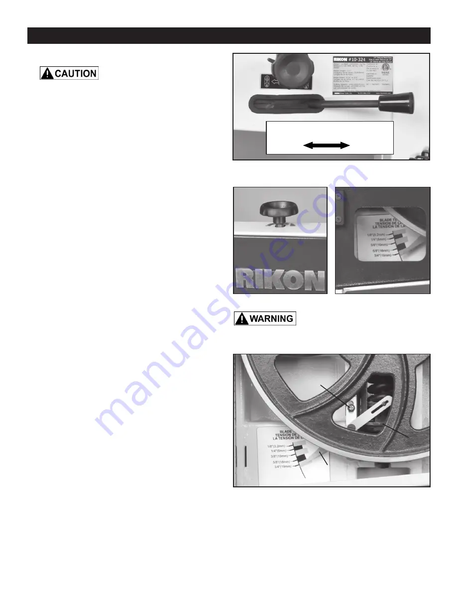
2. To adjust the blade tension, turn the Blade Tension
Handwheel (#1D, Fig. 17) on the top of the saw.
To tighten the tension of the blade, turn the hand
wheel clockwise. Tension the blade until the Tension
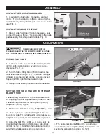
Indicator Arrow (#16A, Fig. 19) corresponds to the
width of blade you are using. View the indicator Arrow
through the top door’s front window. Fig.18.
NOTE:
The blade tension scale may read
differently due to different blade specifications from
manufacturers - steel thickness, material, or variations
in the welded blade length. It may be necessary to
adjust the tension arrow up/down one size on blade
tension scale to match your blade. Note the blade
setting for the next time the same blade is used.
General Rule
for blade tension: With the saw
unplugged and the blade guard up, the saw blade
should deflect about 1/4” when pressed with a finger
to the side of the blade.
See page 16 for information on ‘Adjusting the Blade
Tension Stop’ for tensioning blades that are welded a
bit longer than the specified 111” length.
NOTE:
Excessive counterclockwise turning of the
Blade Tension Handwheel to release blade tension
may unscrew the threaded Blade Tension Rod
(#2C) from its tapped Block (#13C, Fig. 19, C). If
this occurs, blade tensioning is impossible as the
handwheel will just freely turn. The Rod must be re-
threaded into the Block to resume blade tensioning.
ADJUSTING THE BLADE TENSION INDICATOR
The Blade Tension Indicator Arrow (#16A, Fig. 19, A)
should be checked and adjusted the first time the
saw is set up and run, and whenever a new blade is
installed.
The blade tension indicator should be adjusted for
blades made from thicker steel, if over cut or undercut
in length, or made by different manufacturers.
FIGURE 16
FIGURE 17
Quick Release Lever
ON
OFF
FIGURE 18
THE MACHINE MUST NOT BE
PLUGGED IN AND THE POWER SWITCH MUST BE IN THE
OFF POSITION UNTIL ALL ADJUSTMENTS ARE COMPLETE.
A
B
C
1. With moderate tension on the blade, loosen
the Indicator Plate’s adjusting Screw (#14A) with a
Phillips head screw driver (Fig. 19, B).
2. Adjust the blade indicator up/down as needed and
then tighten the plate’s adjusting screw.
Summary of Contents for 10-324TG
Page 43: ...43 OPERATION...


