18
ADJUSTMENTS
Lower Guides -
continued
:
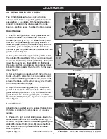
2. The guides should be approximately 1/16” behind
the gullets of the saw blade. If they need to be moved,
loosen the Lever Handle (#60A, Fig. 26, A), located to
the left of the Lower Guide Block (#43A, B), and move
this block that holds the guides so that the guides are
properly positioned behind the blade gullets.
Re-tighten the lever handle when done.
3. Set both bearing guides to within 1/32” of the saw
blade - about the same thickness of a business card.
Do not set the bearing guides too close, or touch the
sides of the blade, as this will adversely affect the life
of the saw blade and bearings.
4. Adjust the rear bearing guide to be just clear of the
back of the saw blade. Release the guide’s Locking
Handle (Fig. 27, C) and move the rear guide towards
the blade by pushing the end of the Rear Guide Shaft
(#45A, D), or use the lock handle to pull the guide
towards the blade. Tighten the handle when done.
ADJUSTING THE BLADE GUIDES - continued
FIGURE 29
FIGURE 28
Approximately
1/4”
ADJUSTING THE BLADE GUIDE & GUARD
NOTE:
Before cutting, set the upper guide bearings
approximately 1/4” above the top surface of the work
piece. This will give the best blade control. Fig. 28.
1. Loosen the Guidepost Lock Knob (#1C, Fig. 30A)
and turn the Guidepost Handle (#38C, Fig. 29, B)
to raise or lower the guide post/upper blade guide
assembly to the desired height.
A measurement scale has been supplied on the right
side of the guide post for quick reference on the height
of the guide bearings above the table surface.
2. When the guide bearings are in proper position,
re-tighten the guidepost lock knob.
NOTE:
The guide post is pre-set at the factory to
aligned vertical with the bandsaw blade. If the guide
post setting ever needs slight adjustment:
3. Open the top door and lower the blade guard all
the way down to the table to access the Guide Bracket
(#4C). Fig. 31.
4. Loosen the four Hex Bolts (#2C) located at the rear
of the top frame. Fig. 30, C). This will allow the
FIGURE 30
CONTINUED ON PAGE 19
FIGURE 26
NOTE: Blade Guard removed for photo purposes
FIGURE 27
NOTE: Blade Guard removed for photo purposes
A
B
A
B
C
D
C
C


