12
ADJUSTMENTS
NOTE:
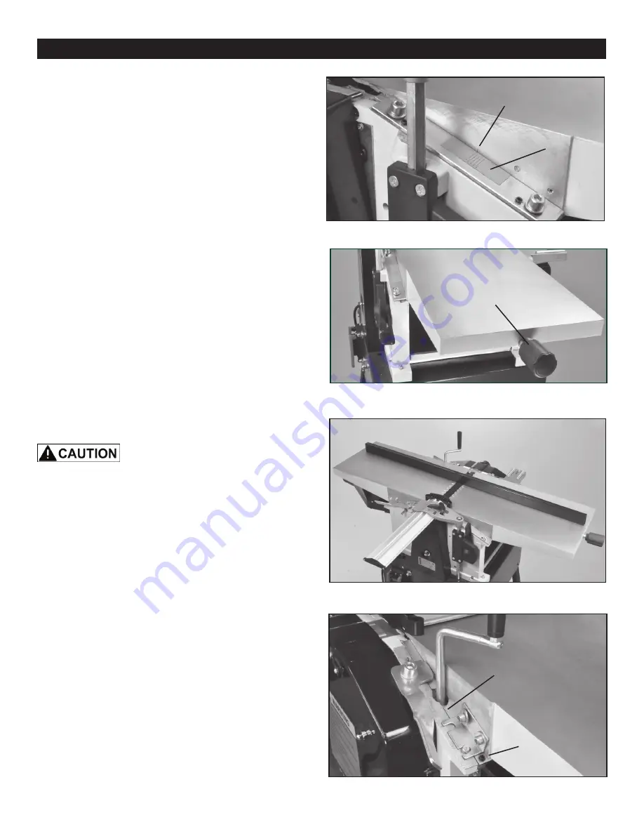
The jointer’s depth of cut can be set by using the
various lines on the scale. The top line is zero and the
bottom line indicates a 1/8” (3mm) cut. It is not advised to
take the deepest cut. Taking multiple cuts of 1/16” or less
produce better finish results, and be much easier on the
machine.
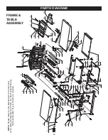
2. To increase or decrease the depth of cut, simply rotate
the infeed adjustment knob. FIG. 16.
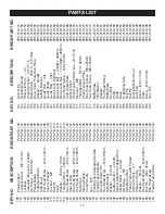
FIG. 17
FIG. 16
OUTFEED TABLE ADJUSTMENT
Check the Outfeed Table to ensure that it is aligned
with the cutterhead and infeed table. Make adjustments
to the outfeed table as follows;
This procedure involves close contact
with the planer blades. Wear gloves to prevent injury to the
hands. Make sure that the machine is disconnected from
the power supply.
In order to accurately set the machine, it is first necessary
to align the tables.
1. Set the infeed table to the ‘0’ setting on its depth of cut
scale (see Infeed Table Adjustment above, FIG. 15).
2. Rotate the cutterhead so that the planer blades do not
interfere with the measurements that will be taken.
3. With a long metal straight edge, place it length-wise
along the outfeed table so that it extends onto the infeed
table. The straight edge should lie level across BOTH
tables. FIG. 17. They should be set at the same height and
perfectly level to each other.
- If it does, the tables are true to each other.
- If the straight edge does not lie flat across both tables,
then the tables must be adjusted. Tune the outfeed table,
as the infeed table was factory set to the cutterhead.
3. Adjust the ANGLE and tilt of the outfeed table with the
hex Guide Screws (#160) located on the rear areas on both
of the Guide Rails (#159 ,161). FIG. 18.
FIG. 15
INFEED TABLE ADJUSTMENT
The Infeed Table is preset at the factory to be aligned with
the cutterhead. To ensure that both the infeed and outfeed
jointer tables are aligned, check both table settings and
adjust the outfeed table as necessary.
1. The infeed table should be set to the upper line on the
Depth Scale. There is a thin Line cut into the metal side of
the infeed table for indicating the table position with the cut-
terhead for regulating the depth of cut. FIG. 15.
FIG. 18
DEPTH OF CUT
ADJUSTMENT KNOB
INDICATOR LINE
DEPTH SCALE
GUIDE SCREW
GUIDE RAIL
OUTFEED
TABLE
Summary of Contents for 25-010
Page 31: ...31 WARRANTY...


