ADJUSTMENTS
14
PLANER HEIGHT ADJUSTMENT
FIG. 22
FIG. 23
FIG. 18
Height adjustment of the planer’s table is made with the
Handle (#130, FIG. 22, A). One full turn of the crank
changes the height of the Planer’s Table (#142, B) by 1/8”.
- Clockwise Turning = raises the planer bed
- Counter-Clockwise Turning = lowers the planer bed.
The planing thickness is indicated on the Scale (#150, C).
A maximum of 1/8” material can be
removed in one pass through the planer. Do not exceed
this depth of cut or damage to your machine may result.
The maximum thickness of stock to be planed is 6-1/4”,
and the maximum width of boards is 10” wide.
A
B
C
PLANER TABLE ALIGNMENT
The machine has been factory set before shipping - the
planer’s table being set parallel to the cutterhead knives.
But once the machine has been set in its final location in
the shop, the table alignment should be checked to make
sure that there has been no movement during its handling.
WARNING:
When working on, or near the machine’s bed,
avoid the risk of personal injury by cuts that may result from
touching the planer knives’ sharp edges!
1. Make sure that the planer/jointer’s switch is turned off,
and the plug is disconnected from the power source.
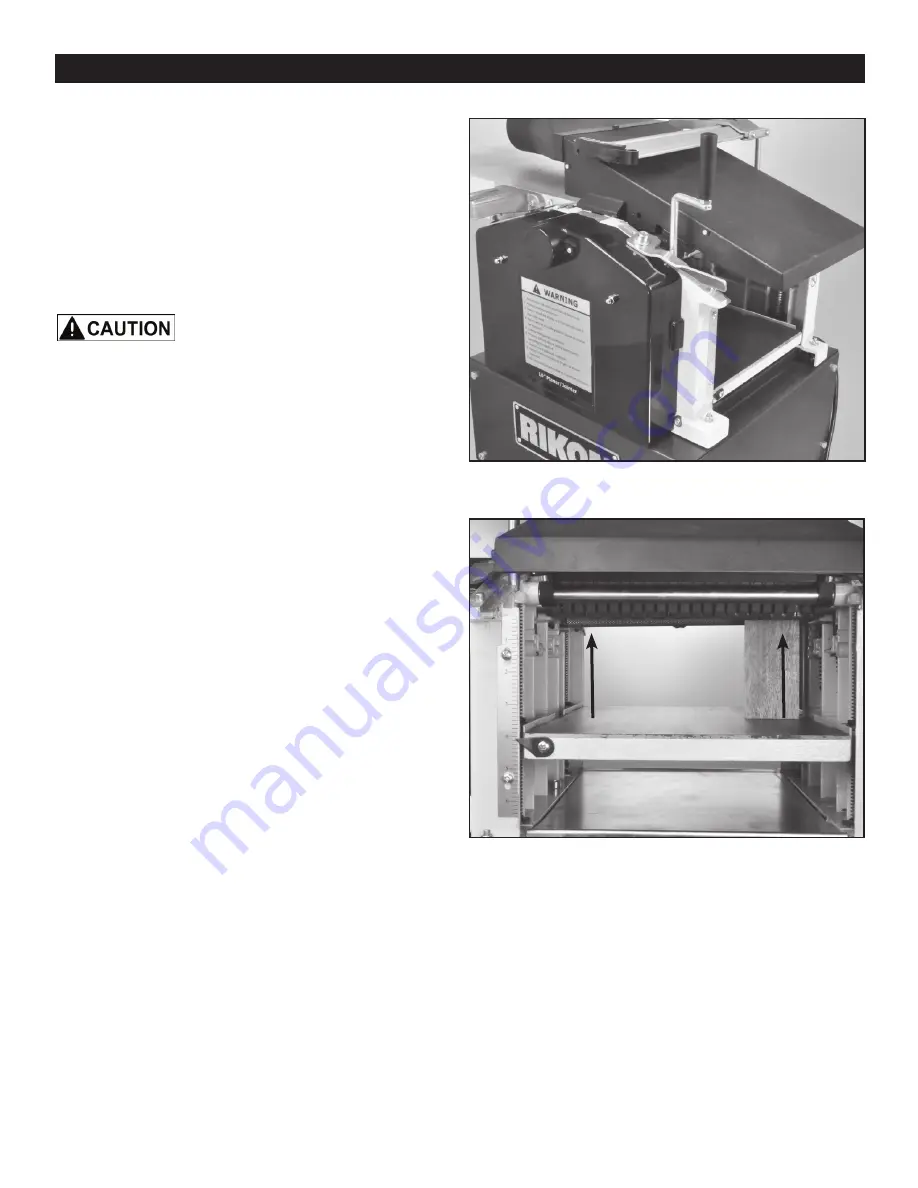
2. So that adjustments can be made, remove the fence
assembly, the cutterhead guard needs to be lifted up, and
the Dust Hood (#194) pivoted onto the infeed table into the
planing use position. FIG. 22.
NOTE:
The cutterhead is fixed in position and any adjust-
ments must be made through the table’s setting.
3. To confirm that the planer table is set parallel to the
cutterhead, measurements from the table surface to the
underside of the cutterhead are made. The distance from
the far right side of the planer’s table should be the same
as the distance taken at the far left of the table.
4. Place a Gauge Block (FIG. 23), or other measuring tool,
onto the planer table, directly under the cutterhead.
5. Raise the table until with the handle until the gauge
block makes contact with the cutterhead knives, or the solid
body of the cutterhead cylinder.
6. Move the gauge block to the other side of the table to
check to see if the gauge block is at the same measure-
ment. If the distance is not the same, then the planer table
has to be adjusted to make up this difference.
NOTE:
Care must be taken to make the measurements at
the same spot on the either end of the head. This may re-
quire that the cutterhead be rotated so that the gauge block
comes in contact with either the knives or the cutterhead
body, same as was used on the first measurement taken.
Summary of Contents for 25-010
Page 31: ...31 WARRANTY...


