8
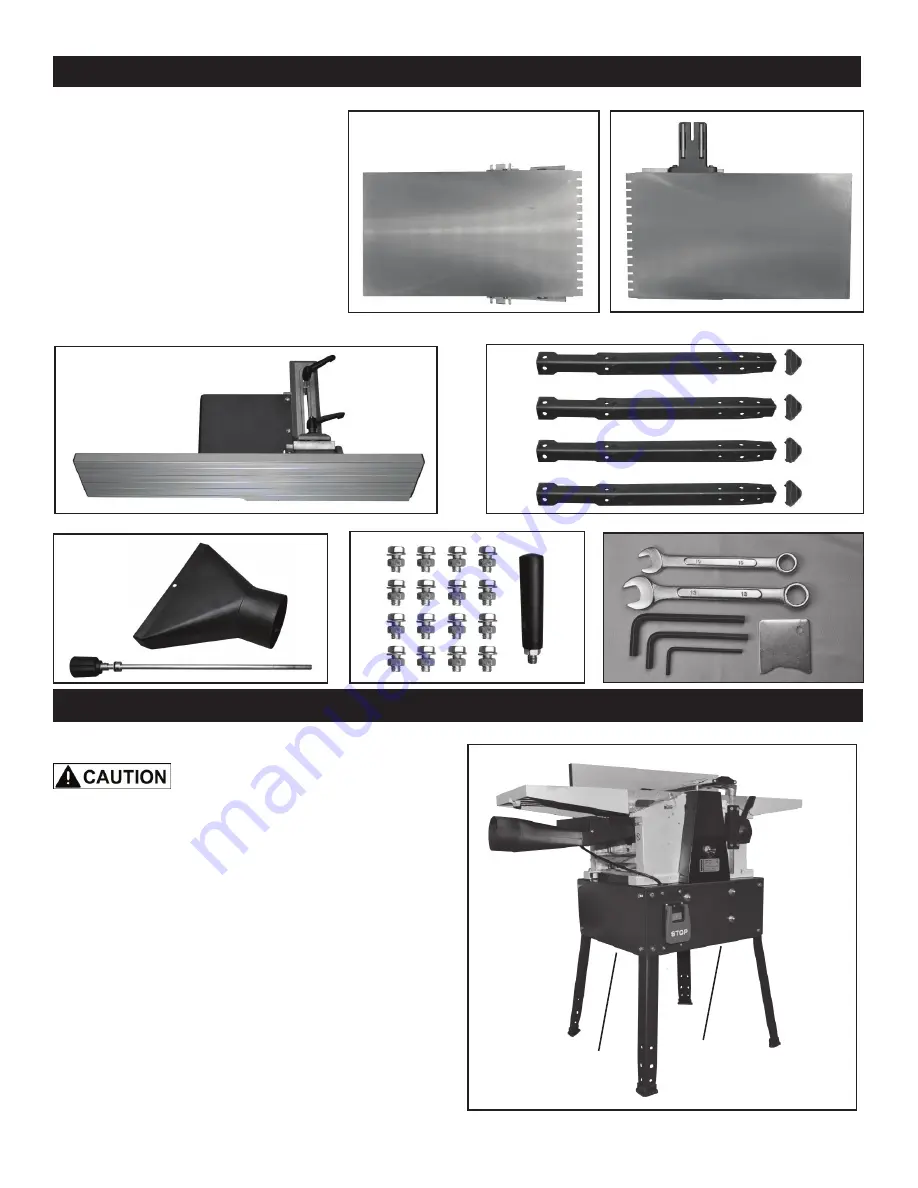
CONTENTS OF PACKAGE
FIG. 1
A. Outfeed Table
B. Infeed Table
C. Fence Assembly
D. Legs & Floor Pads
E. Dust Hood
F. Depth of Cut Control Bar
G. Nuts & Bolts for Leg Assembly
H. Handle
I. Tools a. - Wrenches - 10 & 13mm
b. - Knife Setting Gauge
c.
-
Hex Wrenches - 3, 4 & 5mm
LIST OF LOOSE PARTS
a
b
c
E
A
B
C
D
F
G
H
MOVING & INSTALLING THE PLANER
When moving the planer/jointer, lift
and move the machine with your hands holding the
undersides of the machine’s body. FIG. 1, A. DO NOT
move or carry the planer/jointer with the infeed and
outfeed tables, as this may damage the machine.
1. Position the machine on a solid, level foundation that
is located in an area that ample space in front and in back
of the planer/jointer for the moving of lumber to be milled.
Align the machine so that during use, any kickback will not
face aisles, doorways, or other work areas that bystanders
may be in. Do not locate or use the machine in damp or
wet conditions.
2. For best operation, the Planer/Jointer should be
directly plugged into a power source, without the use of
extensions.
3. The use of a industrial Dust Collector with a minimum
of 650 CFM suction is recommended for chip removal.
A
INSTALLATION
A
I
Summary of Contents for 25-010
Page 31: ...31 WARRANTY...


