14
ADJUSTMENTS
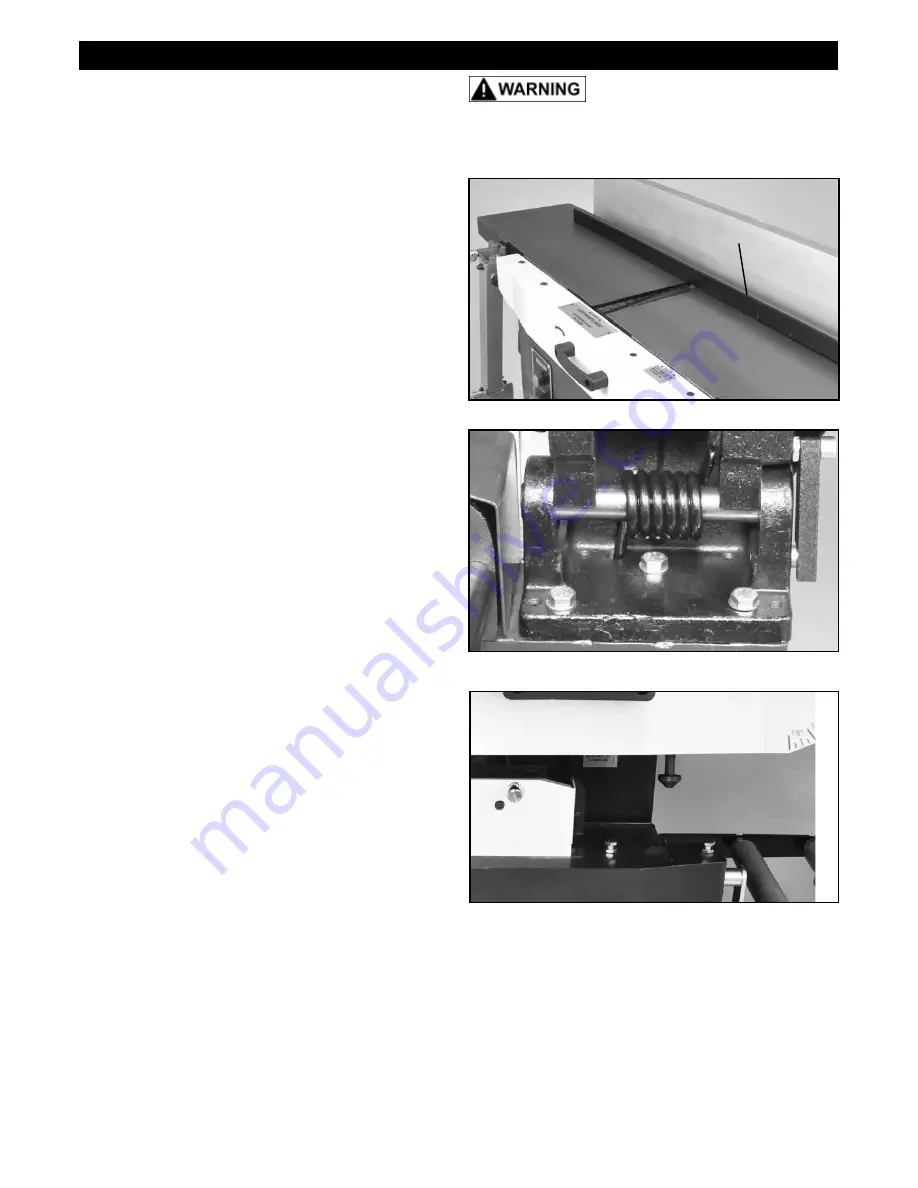
FIG. 21
ADJUSTING THE INFEED TABLE
The Infeed Table is pre-set by the factory to align with
the cutterhead's knife inserts. Should an adjustment be
required, the following steps are needed.
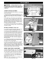
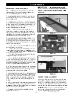
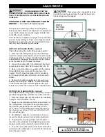
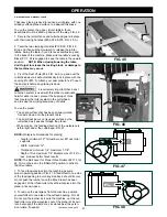
1. Raise the infeed table to its highest, 0", level and use
a metal straight edge to check its level flatness with the
outfeed table. FIG. 21.
2. The jointer table, with the fence and cutterhead guard,
needs to be lifted up and back into a vertical position. See
page 21, steps 1 & 2, for full details on this process. The
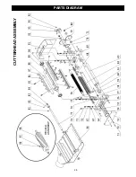
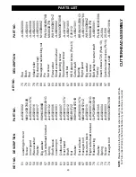
Dust Chute (#66) should be left in the down, jointer-use
position so adjustments can be made.
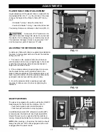
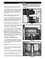
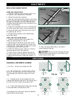
3. With the table up, the Support Base (#120) for the
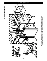
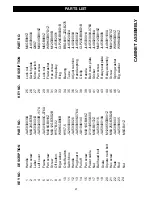
infeed table is exposed. The base has three Hex Bolts
(#132) and four Set Screws (#134) that fasten the table to
the cabinet. The set screws can be adjusted to slightly tilt
the table to align it with the infeed table. FIG. 22.
3. Slightly loosen the three hex bolts so that the set
screws can be adjusted. With small 1/8 or 1/4 turns of the
set screws, tilt the table as needed. A clockwise turn will
advance the set screw, a counter-clockwise turn will retract
them from the base casting.
- The pair of 2 set screws to the far left will raise the left
end of the table. FIG. 22, A & B.
- The pair of 2 set screws to the far right will raise the
forward edge of the table, nearest the cutterhead. C & D.
- The pair of screws furthest back in the base will tilt the
back of the table upward. B & C.
- The pair of 2 set screws at the front of the base will
lift up the front edge of the table. A & D.
- The table can also be tilted down, or up, towards a
specific corner should the situation arise. Three of the set
screws would be adjusted for this. Example: To tilt the far
left corner of the table up, set screws D, then A & C would
be turned. Screw B would be the 'pivot point'
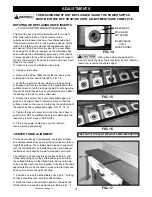
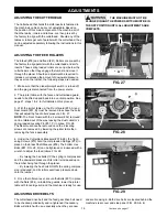
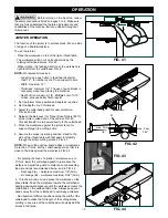
4. The table can also be tilted forward or back with the two
Special Bolts (#18, FIG. 23, E & F). The combination of the
six bolts and screws (A-F) provide a great range of table
positioning to level it with the infeed table.
5. Once adjustments are made, the infeed table should be
checked for flatness with the outfeed table with a straight
edge. FIG. 21. This may require a few attempts to get the
tables in alignment. When the infeed table is flat to the
outfeed table, the hex bolts can be tightened to lock the
settings.
6. With the table lowered, make sure the two safety Table
Locks (#104, G) will engage. These special bolts can be
adjusted up or down by their threaded ends, then secured
with their attached Nuts (#106). FIG. 23.
7. Re-adjust, or install the fence and guard, then the
machine is ready for use.
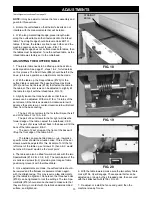
THE MACHINE MUST NOT BE
PLUGGED IN AND THE POWER SWITCH MUST BE IN
THE OFF POSITION UNTIL ALL ADJUSTMENTS ARE
COMPLETE.
FIG. 22
PLANER TABLE ALIGNMENT
The machine has been factory set before shipping - the
planer's table being set parallel to the cutterhead knives.
But once the machine has been set in its final location in
the shop, the table alignment should be checked to make
sure that there has been no movement during its handling.
WARNING:
When working on, or near the machine's bed,
avoid the risk of personal injury by cuts that may result
from touching the knife inserts' sharp edges!
Continued on page 15
FIG. 23
A
B
C
D
E
F
G
STRAIGHT
EDGE

