ADJUSTMENTS
16
FIG. 24
FIG. 26
FIG. 27
DISC TABLE ADJUSTMENTS
Ensure sander is disconnected from the power
supply prior to commencing work.
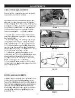
1. To check the trueness of the 90º angle of the
disc sanding table, place a square or other
measuring device on the table with the other end
against the sanding disc. FIG. 24.
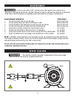
2. Loosen the disc table adjustment Handle
(#25), and adjust table angle to 90º.
3. Re-tighten the disc table adjustment handle.
4. Adjust the Angle Scale Pointer (#16) to 0°.
5. To adjust the disc table to another angle,
loosen the disc table adjustment handle.
6. Set the table at the desired angle using the
angle scale pointer.
7. Re-tighten the disc table adjustment handle.
BELT TABLE ADJUSTMENTS
Ensure sander is disconnected from the power
supply prior to commencing work.
For most sanding operations, the table will likely
remain at a 90º angle to the belt. A positive stop
is provided with your sander to ensure fast
positioning of the table at 90 degrees to the belt.
1. Loosen the table-locking Handle (#25).
2. Position the table back to the platen so there is
about 1/16” space between it and the belt.
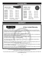
3. Using a square, protractor or other 90º tool,
measure the angle of the table against the Platen
(#67). FIG. 26. Once the 90º is setting is found,
lock it in place, then adjust the hex Set Screw
Stop (#80), that extends under the table.
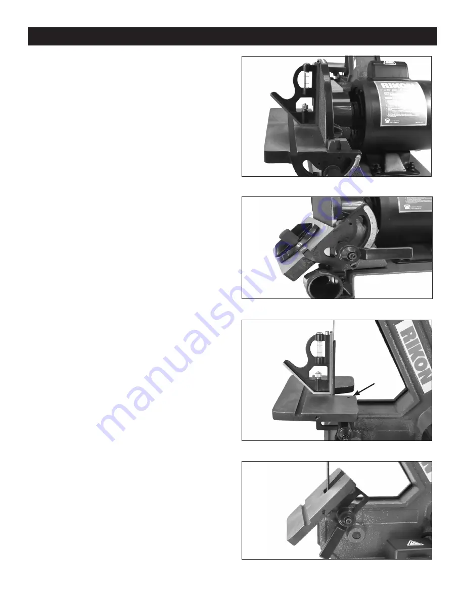
4. To set the table to a different angle, loosen the
handle and tilt the table forward until it is at the
required angle. FIG. 27.
5. Tighten the handle to lock the table in position
for sanding.
NOTE:
To get the full range of table angling,
handle must be very loose, so that it slides along
the slot in the table bracket. The table can then
be moved back to get maximum angles.
FIG. 25
TABLE
STOP
SET SCREW
ADJUSTMENTS


