17
ADJUSTMENTS
V-BELT TENSION ADJUSTMENTS
Ensure sander is disconnected from the power
supply prior to commencing work.
Should the rotation of the sanding belt or disc
slow down or stall, the cause may be that the
V-belt is slipping on the two pulleys. This may be
because the motor or frame have become loose
from the base, or that the V-belt has stretched
out due to the machine being used. In either
case, re-adjustment of the V-belt is needed.
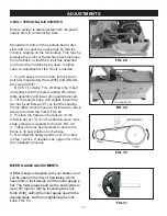
1. To gain access to the V-belt, remove the V-
belt rear metal Safety Plate (#39) and V-Belt &
Disc Guard (#37).
NOTE: For clarity, FIG. 28 shows the V-belt
and pulleys with the metal sanding disc plate,
table assembly and lower disc guard removed.
2. Tilt the sander back, and slightly loosen the
two hex head Screws (#7) so that the sanding
Frame (#64) can be moved a bit forward or back
-
wards to tension the V-belt. FIG. 29.
3. Position the frame so the tension on the
V-belt is about 1/4” to 1/2” deflection when mod
-
erate pressure is applied to the belt. FIG. 30.
4. Tighten the hex head screws to secure the
frame in its new position on the base.
5. Re-install the safety guards over the V-belt,
in step 1 above. If needed, see pages 9 & 10 for
the installation process.
FIG. 28
FIG. 30
FIG. 29
LOOSEN BOLTS
FIG. 31
MITER GAUGE ADJUSTMENTS
A Miter Gauge is supplied with your sander, and
can be used on the disc or belt tables, which
have slots in their design to fit the miter gauge’s
bar. The miter gauge head can be set anywhere
up to 45º (right or left) by loosening the Lock
Knob (#30), setting the miter gauge head to the
desired angle, and then retightening the lock
knob. FIG. 31.


