FIG. A
FIG. B
10
ASSEMBLY
ASSEMBLY AND INSTALLATION
Always ensure the sander is
unplugged prior to attempting any assembly,
installation or changing of parts and accessories.
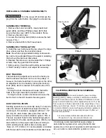
MOUNTING THE SANDER TO A WORKBENCH
CAUTION:
If during operation there is any tendency
for the sander to tip over, slide or walk on the
supporting surface, the sander should be properly
mounted to a workbench or stand.
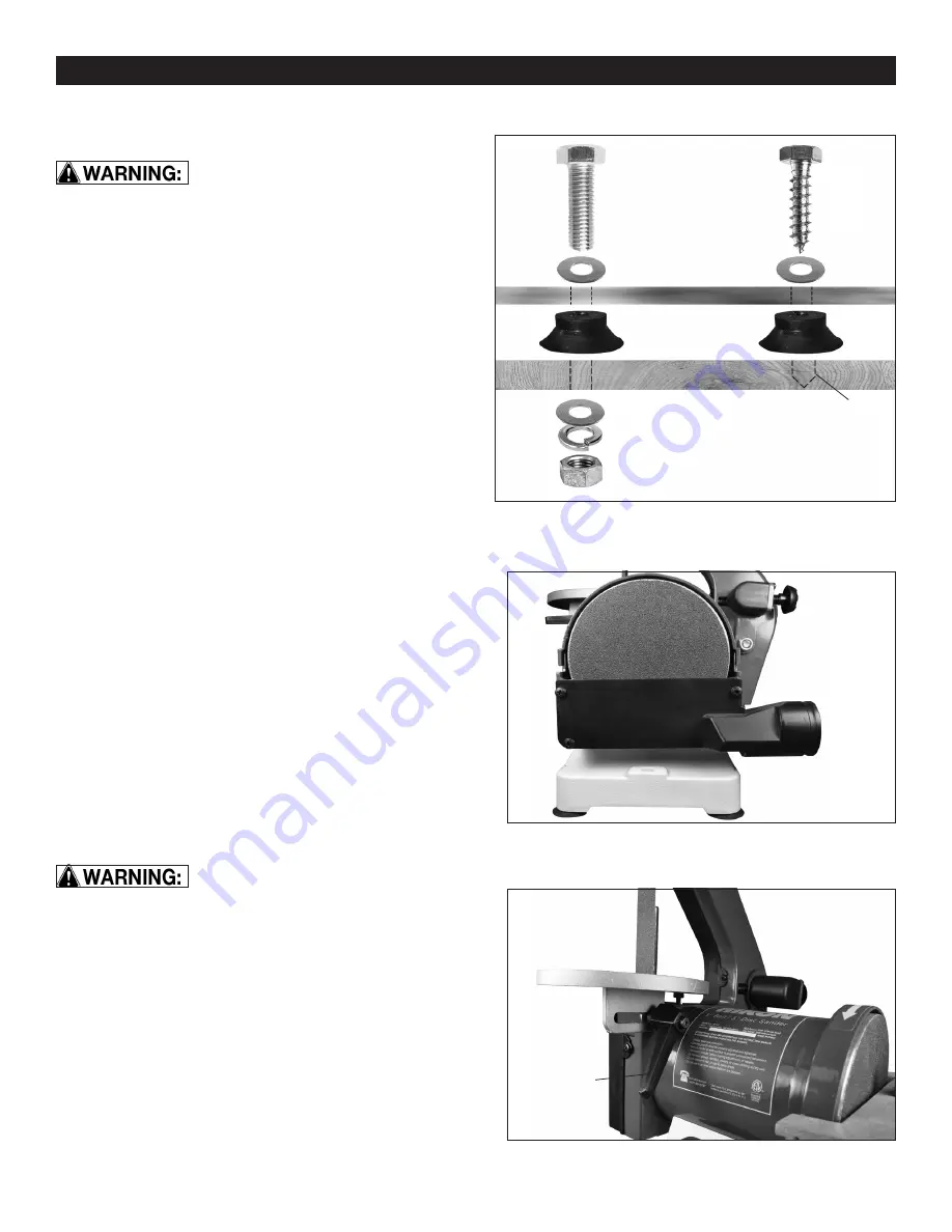
1. Rubber feet are fastened to this sander prior
to shipping. They may, or may not, be used when
attaching the sander to a bench or stand.
2. Position the sander on the workbench.
3. Mark the workbench through the two mounting
holes located in the left and right sides of the sander
base (between the holes for rubber feet).
4. Drill holes in the workbench at the 2 marks.
5. Using long bolts, washers, lock-washers and nuts;
or lag bolts; (fasteners not supplied), secure the
sander to the workbench. FIG. A.
DUST CHUTE INSTALLATION – DISC SANDER
1. Fasten the sanding disc dust-chute and cover
(Part #56) to the machine using the three Phillips M4
screws and washers (#21, 23). FIG. B.
ASSEMBLING THE BELT SANDER TABLE
When assembling the belt & disc
sander, ensure the machine is disconnected from any
power source.
1. Locate the round shaped belt-sanding table (#41).
2. Position the table by threading the belt and plate
through the table’s slot and square opening.
3. Fasten the table to the frame by using the table-
adjustment knob and 8mm washer (#43, 42). FIG. C.
4. Bring the adjustment knob’s screw through the slot
in the bracket opening on the underside of the table,
then into the threaded hole in the frame that houses
the hex nut (#17).
5. Fasten the table in place by using the adjustment
handle to turn its integral screw into the nut.
FIG. C
Dust Chute
Table
Adjustment
Knob
Lag Bolt
Machine Bolt
Washer
Machine Base
Rubber Foot
Washer
Lock Washer
Nut
Pilot Hole for
Lag Bolt
Workbench
Summary of Contents for 50-151
Page 17: ...PARTS EXPLOSION 17...
Page 19: ...WARRANTY 19 WARRANTY...


