background image

SYMPTOM

PROBABLE CAUSE

CORRECTIVE ACTION

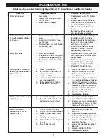
Burn marks on workpiece.

1.  Using a sanding grit that is too 

fine.

2.  Using too much pressure.

3.  Work held still for too long 

against the sandpaper.

1.  Use a coarser-grit sandpaper.

2.  Reduce work piece pressure on 

the sandpaper while sanding.

3.  Do not keep the work piece sand-

ing in one place for too long.

Deep sanding grooves or 

scars in work piece.

1.  Sanding belt/disc grit is too 

coarse for the desired finish.

2.  Work piece is being sanded 

across the grain.

3.  Too much sanding force on the 

work piece.

4.  Work piece held still against the 

belt-disc for too long.

1.  Use a finer-grit sanding belt or 

disc.

2.  Sand with the grain of the wood.

3.  Reduce pressure on workpiece 

while sanding.

4.  Keep work piece moving while 

sanding.

Sanding surface clogs 

quickly.

1.  Too much pressure against the 

belt or disc.

2.  Sanding softwood or highly 

resinous woods.

1.  Reduce pressure on work piece 

while sanding.

2.  Use different stock, sandpa-

per grits, or accept that this will 

happen and plan on cleaning or 

replacing belts & discs frequently.

Sanding grains easily rub 

off the belt or disc.

1.  Sandpaper has been stored in 

an incorrect environment.

2.  Sandpaper has been damaged 

or folded. 

1.  Ensure sandpaper is stored 

away from extremely hot & dry 

or damp/humid conditions.

2.  Store sanding accessories flat – 

not bent or folded.

Workpiece lifts up from the 

sanding disc-table.

1.  Sanding on the “up” , right side 

of the disc, where rotation is 

up and away from the table.

1.  Sand on left side of sanding disc, 

where the disc rotates down 

towards the table.

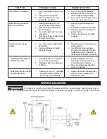
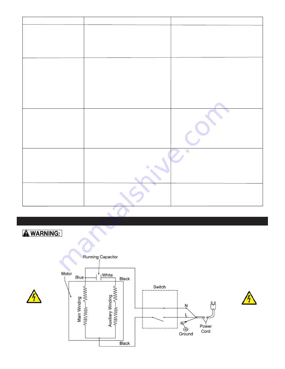
WIRING DIAGRAM


This machine must be grounded. Replacement of the power supply cable should only be 

done by a qualified electrian. Read the Electrical Safety Information on pages 5 and 6 for further information.

16

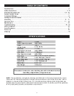
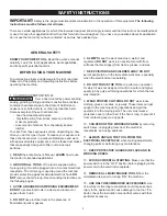
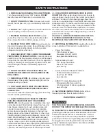
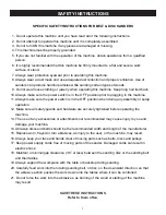
Summary of Contents for 50-151

Page 1: ...al Record the serial number and date of purchase in your manual for future reference Serial Number _________________________ Date of purchase _________________________ For technical support or parts q...

Page 2: ...Disc Speed no load Disc Type Belt Table Size 7 1 4 x 3 7 8 Tilts 45o 1 1 2 Diameter 2 8 1 4 x 6 15 lbs 6 oz Disc Table Size Dust Ports Base Size Net Weight NOTE The specifications photographs drawings...

Page 3: ...our careful attention and understanding The symbol warnings do not by themselves eliminate the danger The instructions and warnings they give are no substitutes for proper accident prevention measures...

Page 4: ...acle The 3rd prong is used to ground the tool and provide protection against accidental electric shock DO NOT remove the 3rd prong See Grounding Instructions on the following pages 4 AVOID A DANGEROUS...

Page 5: ...void breathing the dust and avoid prolonged contact with dust Allowing dust to get into your mouth or eyes or lay on your skin may promote absorption of harmful material Always use properly fitting NI...

Page 6: ...hows a 3 wire electrical plug and electrical receptacle that has a grounding conductor If a properly grounded electrcal receptacle is not available an adapter as shown in FIGURE 2 can be used to tempo...

Page 7: ...machine 11 Always make sure the power switch is in the OFF position when doing any assembly or setup operation 12 Make sure all safety guards and hardware are securely tightened before operating the m...

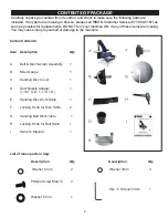
Page 8: ...injury to yourself or damage to the machine CONTENTS OF PACKAGE 8 Carton Contents Item Description Qty A Belt Disc Sander Assembly 1 B Miter Gauge 1 C Sanding Disc Cover 1 D Dust Nozzie Adapter 1 1 1...

Page 9: ...local distributor Clean all rust protected surfaces Do not use gasoline paint thinner mineral spirits etc These may damage painted surfaces Set packing material and shipping carton to the side Do not...

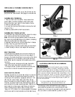
Page 10: ...ners not supplied secure the sander to the workbench FIG A DUST CHUTE INSTALLATION DISC SANDER 1 Fasten the sanding disc dust chute and cover Part 56 to the machine using the three Phillips M4 screws...

Page 11: ...s discon nected from the power supply prior to commencing work For most sanding operations the table will likely remain at a 90 angle to the belt A positive stop is provided with your sander to ensure...

Page 12: ...red angle FIG H 6 Retighten the 2 disc table adjustment handles Note Hook Loop sanding discs cannot be used with this sander Only 5 sanding discs with pressure sensitive adhesive PSA backing can be us...

Page 13: ...use the belt to track to the left towards the side guard DUST CHUTES PORTS Sanding operations are inherently dusty To help min imize the amount of dust that escapes into the sur rounding air this sand...

Page 14: ...upplied with your sander and can be used on the disc table which has a slot in its design to fit the miter gauge s bar The miter gauge head can be set anywhere up to 45 right or left by loosening the...

Page 15: ...me Motor stalls or runs slow resulting in blown fuses or tripped circuit 1 Motor is overloaded 2 Short circuit in the motor or loose connections 3 Low line voltage 4 Incorrect fuses or circuit break e...

Page 16: ...uickly 1 Too much pressure against the belt or disc 2 Sanding softwood or highly resinous woods 1 Reduce pressure on work piece while sanding 2 Use different stock sandpa per grits or accept that this...

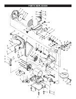
Page 17: ...PARTS EXPLOSION 17...

Page 18: ...3 P50 151 4 P50 151 5 P50 151 6 P50 151 6 P50 151 7 P50 151 8 P50 151 9 P50 151 10 P50 151 11 P50 151 12 P50 151 13 P50 151 13 P50 151 14 P50 151 15 P50 151 16 P50 151 17 P50 151 18 P50 151 19 P50 151...

Page 19: ...WARRANTY 19 WARRANTY...

Page 20: ...www rikontools com 50 151M2 50 151 For more information 16 Progress Rd Billerica MA 01821 877 884 5167 978 528 5380 techsupport rikontools com...

Reviews: