19
9 Operating controls and indicators
26
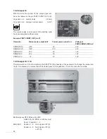
Handles
The generator insert module can be pulled out by
these handles if necessary.
Never pull out or insert the generator insert
module while the unit is connected to the mains.
27
Power bar
Indicates the power delivered during the welding
process.
The maximum power value for the last welding
process is indicated by an LED and then deleted
during the next welding process or if a fault occurs.
29
TEST button
The TEST button is used to:
• Activate ultrasonics for a maximum of 15 s
• Acknowledge error messages.
30
LEDs
•
READY
This lights up when the generator is ready for
operation.
•
US
ACTIVE
This lights up when ultrasonic operation is
activated.
•
ERROR
This lights up if a fault has occurred.
In order make troubleshooting easier, the
error type is indicated through flas
hing of LED 1 to LED 3 on the
power bar (see section 18).
33
The fixing screws of the genera-
tor insert are located above and beneath the
handles
(26)
and must be locked when the unit is
taken into operation.
27
26
33
30
29
26
33


