42
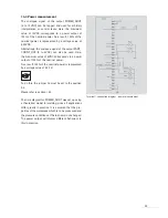
15.3.2 Overview of inputs and outputs
The following table shows an overview of inputs/outputs.
Name Type
Description
Voltage
level
RESET_IN Input Error
acknowledgement,
24VDC
Input current stop = 5 mA typ.
Weld cycle
Input resistance = 8.2 k
Ω
US_ACTIVE_OUT
Output
Ultrasonic process active
24VDC = ultrasonic process active
Output current = 100 mA max.
POWER_AOUT
Output
Analogue power output
0–10 V corresponds to
0W to generator output * 1.2
(e.g. 0 to 2400 W at 2000 W
generator)
Accuracy = ± 3%
Output current = 10 mA max.
READY_OUT
Output
Generator is ready for the
24VDC = ready
next ultrasonic process
Output current = 100 mA max.
AMPL_AIN
Input
Analogue amplitude selection
3–10 V corresponds to an amplitude
of 30% to 100%
Accuracy = ± 3%
Input current = 0.3 mA typ.
Input resistance = 33 k
Ω
MV_OUT
NPN Output
Solenoid valve
Output current = 0.25 A max.
PART_COUTNT_OUT NPN Output
Counter output
Output current = 40 mA max.
Option: analogue
Option: 0 - 4 V corresponds to
line output
0 W to
generator power * 1.2
START_EXT_IN
Input
Starts the ultrasonic process
24VDC = activates ultrasonic process
Input current = 5 mA typ.
Input resistance = 8.2 k
Ω
US_STOP_1_IN
Input
Stops the ultrasonic process
24VDC = stop
Input current = 5 mA typ.
Input resistance = 3.5 k
Ω
ERROR_OUT
Output
Generator error
0VDC = error, 24VDC no error
Output current = 0.5 A max.


