background image

52

20 Service centre addresses

In the event of any technical faults or welding pro-

blems please contact the RINCO ULTRASONICS AG 

technical customer service team, who will be pleased 

to help.

To enable our service team to provide the best possib-

le assistance we will need the following:

–  Detailed description of the technical fault or wel-

ding problem

-  Designation/name of the device

-  Article no. and series no. of the device 

refer to 

the type plate

Our address:

RINCO ULTRASONICS AG

Industriestrasse 4

CH-8590 Romanshorn 1

Switzerland

Tel.  ++41 71 466 41 00

Fax  ++41 71 466 41 01

www.rincoultrasonics.com

info@rincoultrasonics.com

Summary of Contents for RDG20

Page 1: ...Operating manual Generator RDG20 30 35 40 70 English ...

Page 2: ... suitability of the respective products for specific applications Our general contract conditions apply in this case also with regard to liability The information contained in this manual does not grant the user any intellectual property rights nor any licence assurances Suitable agreements must be made to this purpose Suitability of the products for specific applications must be examined in colla...

Page 3: ...ing and starting operation of the device The device must only be used serviced and repaired by persons who are familiar with the operating manual and the applicable health and safety regulations for the prevention of accidents in the workplace Unit specifications Representative ...

Page 4: ...24 11 3 Soft start and start amplitude 24 11 4 Ultrasonic test 24 11 5 Frequency lock in range 25 11 6 Amplitude selection 25 12 Settings 26 12 1 Dip switches 26 12 2 Jumper J6 28 12 3 Jumper J9 J10 28 13 Amplitude values 29 13 1 Amplitude values for 20 kHz generators 29 13 1 1 Amplitude diagram for 20 kHz generators 29 13 2 Amplitude values for 30 kHz generators 30 13 2 1 Amplitude diagram for 30...

Page 5: ...ational availability of the device it is necessary to observe and follow the notes and instructions in this manual Important If you have any questions regarding your unit please state the exact type designation and the unit series number This can be found on the type plate A on the rear of the generator as well as on page two of this operating manual The design and circuitry of these devices are s...

Page 6: ... can result in seri ous injury or damage to equipment if ignored Danger Indicates hazard warnings which can result in death or very serious injury if ignored Danger High voltage This warns about dangerous voltages Take great care if you see this warning Keeping a safe distance is the best way to stay safe Instruction Wear ear defenders This indicates which protection measures need to be followed a...

Page 7: ...ackaging as evidence 2 2 Damage during transit The transport company is responsible for damage occurring during transport A complete report descri bing the exact damage must be submitted to the trans port company this will subsequently serve as the basis for the claim for damages We must be notified immediately of any damage to or loss of the goods we have supplied this must be con firmed by a cop...

Page 8: ...00 W 1900 VA RDG40 400P 230 480 W 400 W 400 W 1100 VA RDG70 100P 230 120 W 100 W 100 W 320 VA 8 3 Technical data 3 1 Standards and conditions of use 3 2 Limit values connected loads Conformity CE Ambient conditions non condensing average relative humidity 20 90 0 to 1000 over NN Temperature range Transport storage 20 to 70 degrees Celsius ambient temperature Operation 10 to 50 degrees Celsius Leak...

Page 9: ...ion about potential hazards which can arise due to ultra sonic welding or cutting For more information about suitable materials please contact RINCO ULTRASONICS AG 4 3 Requirements for use RDG generators are components incomplete machines which are designed for installation in electrical systems or machinery They must not be used as a standalone device They are designed exclu sively for profession...

Page 10: ...s fuses PE connections Additional information can be found in the documentation The documentation contains information about instal lation in accordance with the EMC guidelines Shielding earthing filters and cables wires 4 6 Operation Systems with RDG generators must be equip ped with additional monitoring and protec tion devices which meet the applicable standards e g standards for technical inst...

Page 11: ...al installation 5 1 1 Dimensions and assembly The RDG generator weighs approx 9 5 kg and has the installation dimensions shown in the diagram below For more information please contact RINCO ULTRASONICS AG 11 285 mm 430 mm 150 mm ...

Page 12: ...ambient temperature The permissible ambient temperature range is 10 C to 50 C The RDG generator must be installed in such a way that its maximum permissible temperature is never exceeded The ambient temperature must be monitored In the event that the stated temperature limits are exceeded corresponding temperature control mea sures must be put in place cooling etc Cooling should generally be provi...

Page 13: ... STO_3 Actuator optional STO_5 Start STO_2 Interface optional STO_4 Converter connection STO_0 Mains connection STO_3_1 No function STO_6 No function STO_1 No function Screw the equipotential bonding wire to the PE con ductor connection Please refer to sections 5 3 2 and 5 3 3 Only use an earthed mains connection For more information about pin assignment refer to section 10 1 Attachment for the eq...

Page 14: ...r a cable with a minimum cross section of 6 mm 5 4 EMC compliant installation RINCO ULTRASONICS AG has performed conformity tests with the RDG type generators on specific defined vibration units Ultrasonic systems which have been assessed in this way are referred to as CE typical ultrasonic systems in the following 5 4 1 Installation of a CE typical ultrasonic system The following points must be o...

Page 15: ... defen ders by attaching a corresponding warning sticker to the machine or he must ensure that the operator is protected against arising noise emissions through the use of a sound enclosure Sound components in the audible range are deemed to be potentially harmful to hearing if the energy equivalent continuous sound pres sure level Leq reaches a level of 88 dB A ormore inrelationtoarepresentativew...

Page 16: ...M Swiss Association of Machinery Manufacturers The requirements for fulfilment of the guarantee condi tions by RINCO ULTRASONICS include the following The user must be familiar with the content of this operating manual The instructions and warnings contained in this operating manual must be observed Unauthorised modifications or conversions to parts of the device the oscillator system and the gene...

Page 17: ...output 0 120 0 4 V 0 10 V Increased process reliability thanks to active pro cess monitoring Digital open and closed loop con trol technology designed according to the latest findings in the field of ultrasonic welding technology Welding controlled via a digital signal processor DSP Digital PLL for frequency control Amplitude control Power measurement with an accuracy of 1 of the rated generator p...

Page 18: ... 20 kHz 2000 W 1500 W 1000 W 30 kHz 1000 W 500 W 35 kHz 750 W 400 W 35 4 kHz 900 W 750 W 400 W 200 W 40 kHz 800 W 400 W 70kHz 100 W for 4PZT converter The vibration units and generators should only be procured from RINCO ULTRASONICS AG For applications involving high loads the internal cooling should be adapted to the ambient condi tions For more information please con tact your nearest RINCO ULTR...

Page 19: ... or if a fault occurs 29 TEST button The TEST button is used to Activate ultrasonics for a maximum of 15 s Acknowledge error messages 30 LEDs READY This lights up when the generator is ready for operation US ACTIVE This lights up when ultrasonic operation is activated ERROR This lights up if a fault has occurred In order make troubleshooting easier the error type is indicated through flas hing of ...

Page 20: ...nnectors on the rear panel of the generator Only original RINCO ULTRASONICS AG components must be used for this Otherwise the overall system may fail to work properly 10 1 Signals All digital and analogue inputs and outputs can be tapped via the connectors In the process the prescri bed wiring for the generator which is used must always be adhered to Plug connection rear panel ...

Page 21: ...mA can be applied to this output Alternatively this output can be used to measure the current power 0 4VDC The maximum output voltage of 4VDC corresponds to 120 of the generator power Please refer to section 12 2 21 10 2 Description of the signals The available signals are briefly described below The time behaviour of the signals is described in section 15 3 4 10 2 1 STO_0 Voltage supply of the RD...

Page 22: ...ormally ERROR_24VDC_IN and ERROR_OUT are short circuited via relay contacts If a fault is present this connection is interrupted A maximum of 24V 0 5A can be applied to this output HOMEPOS_24VDC_IN HOMEPOS_OUT If the input HOMEPOSITION_IN is connected to 24VDC then HOMEPOS_24VDC_IN and HOMEPOSITION_ OUT are short circuited via relay contacts READY_OUT If the RDG generator is ready for the next wel...

Page 23: ...DC voltage supply for the emergency stop device START_1_AMP_IN This input can be used to start the welding process The input is high active i e ultrasonic operation is started if 24VDC is present at this input START_2_AMP_IN No function 10 2 5 STO_5 24VDC_EMERGENCY_OUT 24VDC voltage supply for the emergency stop device 24VDC_EMERGENCY_IN Emergency stop input The emergency stop device can be connec...

Page 24: ...amplitude is reached The time from the start amplitude to the target amplitude is referred to as the soft start time and lasts 50 ms At the same time the frequency control is slowed down during the soft start This makes the run up easier on sonotrodes on which it is difficult to build up oscillations The diagram shows the ramp start value and the soft start time The higher level software must prev...

Page 25: ...0 kHz generators The ultrasonic process is aborted with an error message if the lock in range is exited 11 6 Amplitude selection The target amplitude of the RDG generator can be set either internally or externally Whether the internal variable or the analogue input external is to be used is adjusted via a parameter which can be changed via the dip switches Please refer to section 12 1 Amplitude se...

Page 26: ... within the range from 40 to 100 in increments of 10 If the analogue amplitude input is activa ted then the amplitude can be changed exter nally with the voltage 3 10V at AMPL_AIN STO_2 in the range from 30 100 Cable length The cable length can be adjusted to 3 7 and 11 m Slow control rate In the event of oscillation build up problems in the case of larger or more complex sonotrodes the para meter...

Page 27: ... settings Dip switches 1 2 3 4 5 6 7 8 ON OFF ON OFF OFF OFF n c n c The standard settings of the RDG generator are used External amplitude selection Dip switches 1 2 3 4 5 6 7 8 ON ON ON ON OFF OFF n c n c The analogue amplitude input is activated the cable length is 3 m slow control rate is deactivated Internal amplitude selection Dip switches 1 2 3 4 5 6 7 8 ON OFF ON ON OFF OFF n c n c The tar...

Page 28: ...utput in Voltage at PART_COUNT_OUT in V RDG20 2000 1600 80 2 67 RDG30 1000 1000 100 3 33 RDG35 900 360 40 1 33 RDG40 800 400 50 1 67 RDG70 100 30 30 1 00 12 3 Jumper J9 J10 The jumpers J9 and J10 are located on the BUS PCB in the housing of the generator To change the jumper set tings it is necessary to remove the left hand side panel of the generator To do this undo the 6 screws J10 J9 J9 Emergen...

Page 29: ...figuration of the corresponding sonotrode generator booster combination The effective welding amplitude can therefore be read off directly 13 1 Amplitude values 20 kHz generators 9 Sonotrode 24 Converter 25 Booster A Amplitude K1 Interface converter booster K2 Interface booster sonotrode 13 1 1 Amplitude diagram for 20 kHz generators A 24 K1 25 K2 9 ...

Page 30: ...tegrated booster A Amplitude K2 Interface converter sonotrode 13 2 1 Amplitude diagram for 30 kHz generators 24 K2 9 A 500 W converter C30 1 1000 W converter C30 2 100 40 90 80 70 60 50 1 1 1 1 Amplitude m 1 1 V 1 1 5 1 2 1 3 1 4 Horns Integrated booster Gain 100 40 90 80 70 60 50 ...

Page 31: ...mplitude values for 35 kHz generators 9 Sonotrode 24 Converter 25 Booster A Amplitude K1 Interface converter booster K2 Interface booster sonotrode 13 3 1 Amplitude diagram for 35 kHz generators A 24 K1 25 K2 9 ...

Page 32: ...integrated booster A Amplitude K2 Interface converter sonotrode 13 4 1 Amplitude diagram for 40 kHz generators 24 K2 9 A 800 W converter C40 2 400 W converter C40 2 100 90 80 70 60 40 50 1 1 1 1 Horns Amplitude m Integrated booster V 1 1 5 1 2 1 3 1 4 Gain 100 90 80 70 60 40 50 ...

Page 33: ...plitude diagram for 70 kHz generators 24 K2 9 2 4 6 8 3 6 9 12 4 8 12 16 5 10 15 20 V 1 1 1 2 1 3 1 4 1 5 Sonotroden Amplitude µm Verstärkung 1 2 3 4 9 18 27 36 8 16 24 32 7 14 21 28 6 12 18 24 10 20 30 40 1 10 1 9 1 8 1 7 1 6 Sonotroden Verstärkung 1 9 100 7 90 5 80 3 70 8 6 4 2 A Sonotrode amplification Sonotrode amplification ...

Page 34: ...ds to be set back to 0VDC to stop ultra sonic operation The input US_STOP_1_IN serves as a further option for switching off the ultrasonic process The input US_STOP_2_IN must be connected to GND Alternatively the input US_STOP_1_IN can be con nected to 24VDC_IO_IN and the input US_STOP_2_IN can be connected to GND to switch off the ultrasound Ultrasonic operation is immediately switched off in the...

Page 35: ... The diagram shows the basic circuit for starting ultrasonic operation via the digital input START_1_ AMP_IN To start the signal is set to 24VDC and the signal needs to be set back to 0VDC to stop ultrasonic operation 35 ...

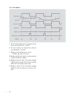
Page 36: ...Oscillator generator or limit error 3 Welding stopped by applying 24VDC to US_STOP_1_ IN A US_STOP_1_IN must be present for 5 ms before the stop is executed B The signal level of START_EXT_1 is not relevant C The solenoid valve output is activated immediately after the start of ultrasonic operation and deactiva ted immediately after the stop of ultrasonic operati on ...

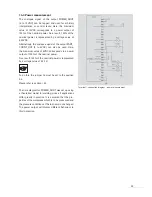
Page 37: ...to 100 If the analogue signal is below the value for the start amplitude 30 the generator will report a fault The amplitude can be changed at any time The generator must be parameterised for external amplitudes by setting dip switches Please refer to section 12 1 Terminal connection diagram amplitude selection Error Ready ...

Page 38: ...elding was aborted because of an error Oscillator generator or limit error A Welding is performed at 80 of the target amplitu de 80 corresponds to 8VDC B Welding is started at 100 of the target amplitude 10VDC and then reduced to 40 of the amplitude 4VDC after the required period of time C Welding is started at 40 of the target amplitude 4VDC and then consistently and linearly incre ased ...

Page 39: ... value of 4VDC corresponds to a power output of 120 of the nominal power As a result 100 of the nominal power is represented by a voltage value of 3 33 V To do this the jumper J6 must be set to the position 3 4 Please refer to section 12 2 The time diagram for POWER_AOUT was set up using a theoretical model for welding since all applications differ greatly in practice It is assumed that the pro pe...

Page 40: ...out the entire welding time In the theoretical model the power depends on the amplitude and remains constant in the process B The welding is started at 70 of the target amplitu de 7VDC this is then increased to 100 amplitu de 10VDC in the required time In the theoretical model the power depends on the amplitude and therefore also jumps up The power value 0 to 10VDC varies according to the applicat...

Page 41: ...0mm Generatortyp Sicherung F1 6 3x32mm Sicherung F2 5x20mm RDG20 2000P 230 12 5A 12 5A UGI20 2000P 230 12 5A RDG20 1500P 230 10A 10A UGI20 1500P 230 10A RDG20 1000P 230 10A 10A UGI20 1000P 230 10A RDG30 1000P 230 10A 10A UGI30 1000P 230 10A RDG30 500P 230 4A 4A UGI30 500P 230 4A RDG35 4 900P 230 6 3A 6 3A UGI35 4 900P 230 6 3A RDG35 750P 230 6 3A 6 3A UGI35 750P 230 6 3A RDG35 4 750P 230 6 3A 6 3A...

Page 42: ...the 24VDC ready next ultrasonic process Output current 100 mA max AMPL_AIN Input Analogue amplitude selection 3 10 V corresponds to an amplitude of 30 to 100 Accuracy 3 Input current 0 3 mA typ Input resistance 33 kΩ MV_OUT NPN Output Solenoid valve Output current 0 25 A max PART_COUTNT_OUT NPN Output Counter output Output current 40 mA max Option analogue Option 0 4 V corresponds to line output 0...

Page 43: ...rnal resistance of the supply source must not exceed 330 W In order to prevent the generation of errors at the analogue power output POWER_AOUT Pin R or PART_COUNT_OUT the internal resistance of the connected drain must be greater than 10 kW In order to be able to use the analogue power output at the pin PART_COUNT_OUT jumper J6 must be set to the position 3 4 Please refer to section 12 2 AMPL_AIN...

Page 44: ..._IN Pulse Width Low tUS_ON_LO 200 ms US_STOP_1_IN Pulse Width High tUS_STOP_HI 5 ms US_ACTIVE_OUT High tUS_ACTIVE_HI tUS_ON_HI 5 ms START_EXT_1_IN High to tOn1 105 2 105 8 ms US_ACTIVE_OUT High Delay START_EXT_1_IN Low to tOff2 0 5 1 ms US_ACTIVE_OUT Low Delay US_STOP_1_IN High to tOff3 5 2 5 8 ms US_ACTIVE_OUT Low Delay US_READY_OUT Low tUS_READY_LO tUS_ON_HI 5 ms START_EXT_1_IN High to tOff1 105...

Page 45: ...ng to the operating environment for dust and cleaned as required If filters are provided upstream of the fan then they should be replaced All connecting cables must be checked periodically If any damage to insulation is noted then the affec ted components must be replaced immediately All fastening screws must be properly tightened Before the start of any maintenance or cleaning work make sure that...

Page 46: ...46 17 Disposal The generator must be disposed of properly in accord ance with the applicable legislation and requirements Please contact RINCO ULTRASONICS AG for more information ...

Page 47: ...deleted with a new start signal This means that with these types of error the generator can start a new cycle without the error message needing to be acknowledged first However an acknowledgement is only possible if the fault is no longer active e g if an upper temperature limit is no longer being violated All generator errors must always be acknowledged with the TEST button or with the Reset_IN s...

Page 48: ... voltage supply 24VDC_IO_IN I Os not possible Noise Check the mounting fixtures Check the tightening torques of the oscillator system between converter booster and sonotrode Check the power losses of the oscillator system when not clamped and when clamped if necessary replace the converter booster and or sonotrode Heat Cooling of the converter and sonotrode is recommended depending on the applicat...

Page 49: ...ssage must be acknowledged via the TEST button or via the Reset_IN signal Minimum signal Minimum signal operation Error message is generated Increase amplitude operation of of the output stage due to Ultrasonic process is the output stage defective components in aborted the generator A new ultrasonic process Very low amplitude selection is prevented The error message must be acknowledged via the T...

Page 50: ...ation of high pressure is started at the nominal oscillator system Defect on the oscillator frequency Check the temperature of system the oscillator system Check replace the sonotrode Reduce the welding pres sure Maximum Oscillator system defective Error message is generated Check replace converter converter voltage Excessive damping of Ultrasonic process is sonotrode booster exceeded the oscillat...

Page 51: ...workpiece welding frequency Check the process sequence Check replace the oscillator system Analogue amplitude The voltage at the external Error message is generated Correct the voltage at the too low analogue amplitude Ultrasonic process is external analogue input is below the aborted amplitude input value for the start A new ultrasonic process is amplitude less than started at the last 3V before ...

Page 52: ...ce team to provide the best possib le assistance we will need the following Detailed description of the technical fault or wel ding problem Designation name of the device Article no and series no of the device refer to the type plate Our address RINCO ULTRASONICS AG Industriestrasse 4 CH 8590 Romanshorn 1 Switzerland Tel 41 71 466 41 00 Fax 41 71 466 41 01 www rincoultrasonics com info rincoultras...

Page 53: ...53 Date Work completed Person responsible Notes ...

Page 54: ...RINCO ULTRASONICS AG Industriestrasse 4 CH 8590 Romanshorn1 Switzerland Tel 41 71 466 41 00 Fax 41 71 466 41 01 info rincoultrasonics com www rincoultrasonics com A C R E S T G R O U P C O M P A N Y ...

Reviews: