


- 6 -
6 Technical data
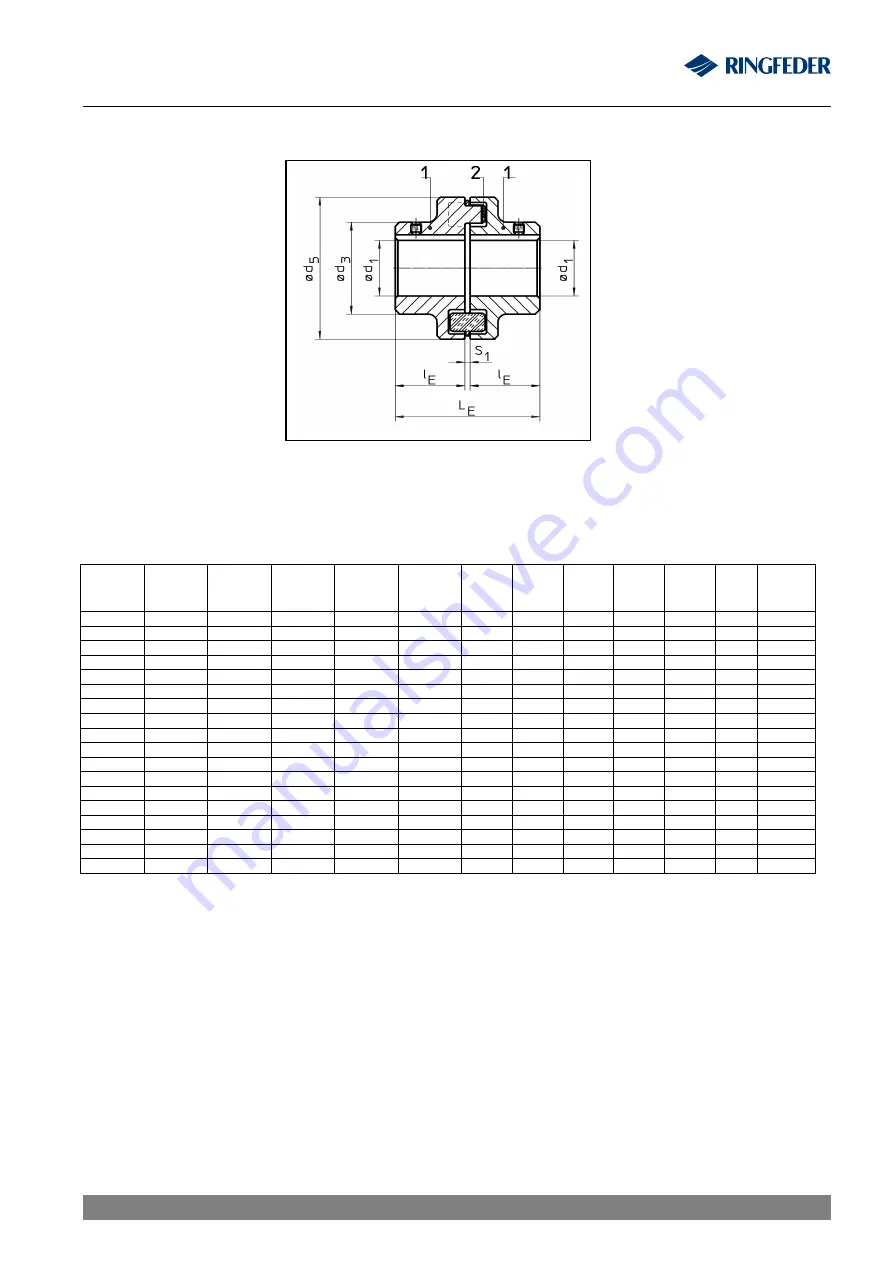
Table 1
Technical data:
Size
TNM
E
T
Cnom
Pb72
[Nm]
T
Cpeak
Pb72
[Nm]
T
Cnom
Pb82
[Nm]
T
Cpeak
Pb82
[Nm]
n
max
[min
-1
]
d
1
max
[mm]
d
3
[mm]
d
5
[mm]
l
E
[mm]
L
E
[mm]
S
1
[mm]
m
unbored
[kg]
50
13
27
20
45
12500
19
33
50
25
52,0
2,0
0,4
67
22
45
35
75
10000
28
46
67
30
62,5
2,5
1,0
82
48
100
75
160
8000
32
53
82
40
83,0
3,0
1,8
97
96
200
150
340
7000
42
69
97
50
103,0
3,0
3,4
112
150
310
230
540
6000
48
79
112
60
123,5
3,5
5,3
128
250
500
380
860
5000
55
90
128
70
143,5
3,5
8,2
148
390
800
600
1350
4500
65
107
148
80
163,5
3,5
12,7
168
630
1300
980
2250
4000
75
124
168
90
183,5
3,5
19,3
194
1050
2000
1650
3630
3500
85
140
194
100
203,5
3,5
27,8
214
1500
3100
2400
5400
3000
95
157
214
110
224,0
4,0
38,2
240
2400
4800
3700
8650
2750
110
179
240
120
244,0
4,0
53,4
265
3700
7500
5800
13500
2500
120
198
265
140
285,5
5,5
75,0
295
4900
10000
7550
18000
2250
130
214
295
150
308,0
8,0
95,7
330
6400
13000
9900
23400
2000
150
248
330
160
328,0
8,0
132,9
370
8900
18200
14000
32750
1750
170
278
370
180
368,0
8,0
187,7
415
13200
27000
20500
49000
1500
190
315
415
200
408,0
8,0
259,3
480
18000
36000
28000
66000
1400
210
315
415
220
448,0
8,0
328,7
575
27000
54000
41000
97500
1200
230
350
575
240
488,0
8,0
466,9
The torque T
Cnom
and T
Cpeak
is valid for:
-
Intermediate rings of Perbunan Pb72 and/or Pb82,
-
Ambient temperatures of -40 °C to +60 °C,
-
Operation within the stipulated alignment values.
During the layout of the coupling according to DIN 740 part 2 (or also
Product Paper & Tech
Paper ”Elastomer Jaw Couplings“
) different factors must be considered:
-
with higher temperatures a corresponding temperature factor S
υ
-
according to the starting frequency a starting factor Sz
-
in dependence of the operating conditions an impact factor, S
A
, S
L
With circumferential speeds of more than 22 m/s, we recommend to balance the coupling.
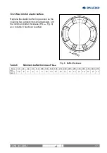
Fig. 2
RINGFEDER
®
TNM E
RINGFEDER
®
TNM E
BAWN 001-
GBR
-1


