- 17 -
9.1 Check of Direction of Rotation
§
Injury danger!
§
Switch-off the drive before all work on the coupling!
§
Secure the drive against unintentional switching on and rotating!
§
Due to incorrectly screwed on screws, parts can fly away and
cause person and material damage!
§
Check before commissioning the coupling the alignment and all
screw fixings for their specified tightening torque and/or firm seat-
ing!
§
Before commissioning the plant all protective devices against
unintentional touching of free moving and/or rotating parts must be
installed.
§
To avoid sparks coverings should be made of stainless steel!
§
The coverings must fulfil at least the protection type IP2X.
§
The covering is to be designed in such a way that it does not
deposit dust onto the coupling parts.
§
The covering must not touch the coupling and/or influence it in its
function.
·
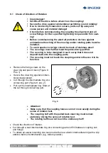
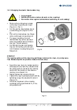
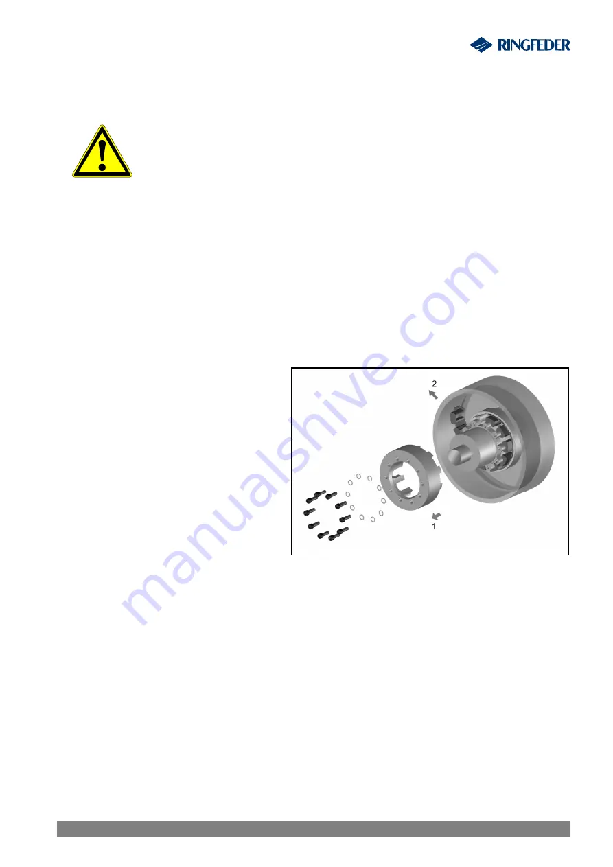
Remove the fixing screws on the
claw ring and push it back (Figure 9,
Pos. 1).
·
Secure the claw ring against uninten-
tional displacement.
·
Cut through the intermediate ring at a
connecting part (Figure 9, pos. 2).
·
Pull out the intermediate ring. Start at
the cut through connecting part.
·
Attention!
·
Make sure, that the coupling halves can not move axially during the
sense of rotation test.
·
The coupling half with the pulled back claw ring must remain
stationary during the sense of rotation test.
·
The rotating half must not touch the stationary half!
·
Check the direction of rotation.
·
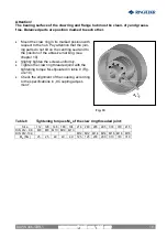
Cut through a new intermediate ring at a connecting part and fit it between coupling hub
and flange.
·
To obtain an easier mounting one can provide the new elastic intermediate ring with a slip
additive before its introduction (e.g. talcum powder).
Fig. 9
RINGFEDER
®
TNM GBT, TNM GTW
BAWN 006-
GBR
-1


