- 21 -
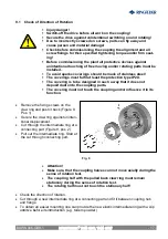
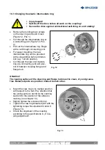
Fig. 12
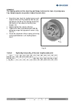
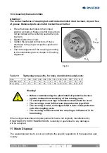
Fig. 13
10.3 Changing the elastic intermediate ring
§
Injury hazard!
§
Switch-off the drive before all work on the coupling!
§
Secure the drive against unintentional switching on and rotating!
·
Remove the holding-down screws
on the claw ring and push it back
(Figure 12, Pos. 1)
·
Cut through the intermediate ring at
a connecting joint (Figure 12, Pos.
2)
·
Pull out the intermediate ring. Begin
at the cut through connecting joint.
·
For easier mounting, the new
intermediate ring can be provided
with a slip additive before introduc-
tion (e.g. Talcum powder).
·
Cut through the new intermediate
ring at a connecting joint and posi-
tion it between coupling flange and
flange hub.
Attention!
The bearing surface of the claw ring and flange hub must be clean, dry and grease-
free. Balanced parts are position marked to each other.
·
Mount the claw ring in its marked position
with respect to the hub. Pay attention that
the joining parts do not tilt on the centring
seat and to the position of the abrasive
marking. (see chapter 10).
·
Slightly tighten the screws uniformly.
·
Tighten the claw ring threaded joint with the
tightening torque M
A
stipulated in table 8
(Figure 13).
·
Check the alignment of the coupling
according to the specifications in „8 Cou-
pling adjustment”.
RINGFEDER
®
TNM GBT, TNM GTW
BAWN 006-
GBR
-1


