- 11 -
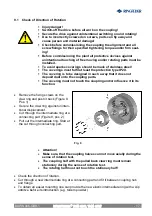
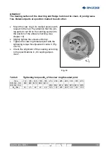
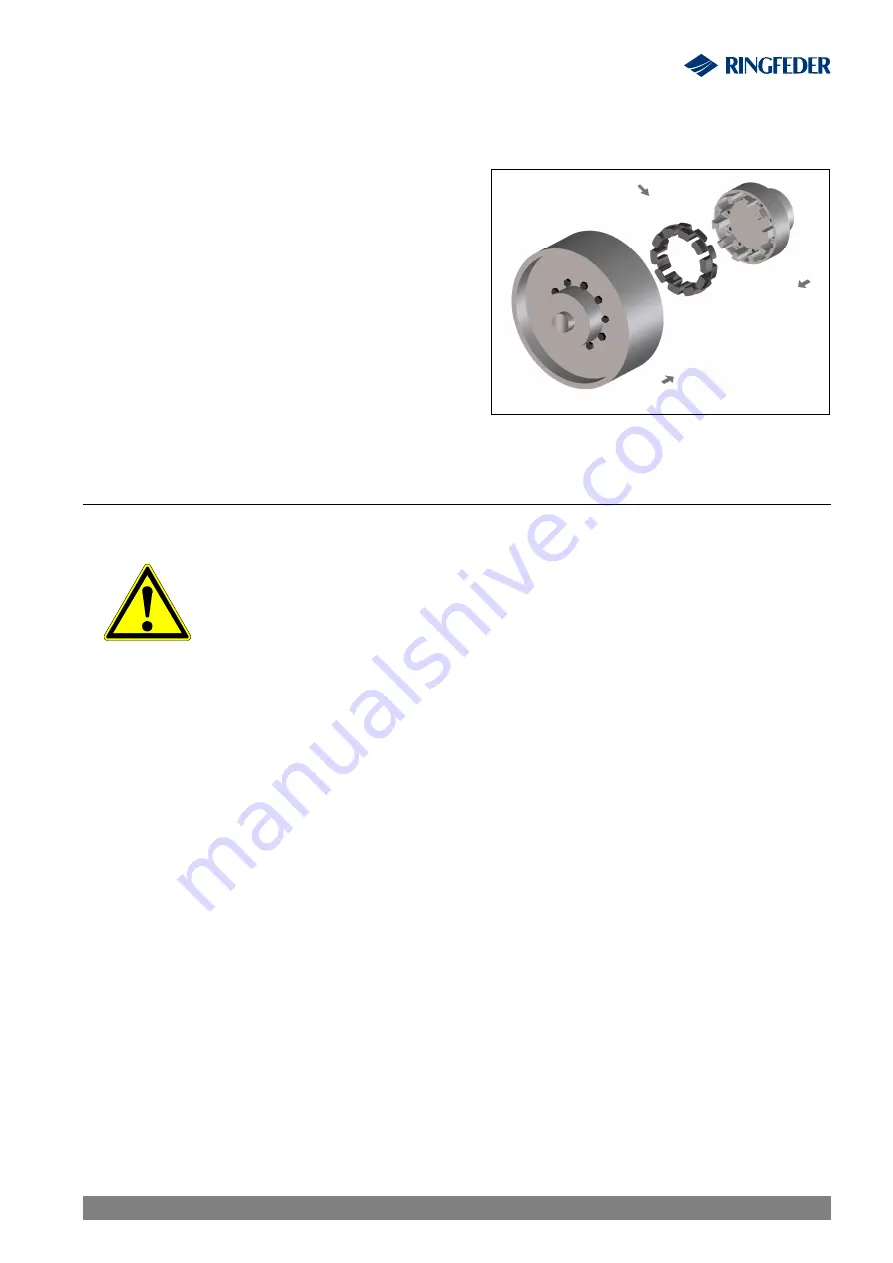
Fig. 5
ATTENTION!
Let the hot hub cool off to ambient temperature before the introduction of the interme-
diate ring.
·
For easier mounting the elastic intermediate
ring can be provided with a slip additive (e.g.
Talcum) before introduction.
·
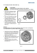
Fit the intermediate ring into one half of the
coupling
·
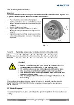
Push the shaft end with the mounted
coupling halves together (Figure 5).
·
Adjust the coupling according to the follow-
ing specifications in “8 Coupling adjustment”.
8 Adjusting coupling
§
Injury hazard!
§
Switch-off the drive before all work on the coupling!
§
Secure the drive against unintentional switching on and rotating!
§
Reference:
§
An exact alignment of the coupling increases the service life of the
elastic intermediate ring.
§
Do not exceed the maximum permissible displacement values. The
overstepping of these values results in coupling damage and
breakdown!
·
When aligning the cold equipment take into account the expected thermal growth of the
components, so that the permissible misalignment values for the coupling are not
exceeded in operation.
·
Be aware that the coupling under misalignment imposes restoring forces on the adjacent
shafts and bearings. Take into account that the larger the misalignment, the greater the
restoring forces will be.
·
The displacements values indicated in the tables 4 to 6 are maximum permissible guide
numbers.
We recommend not to fully utilise these values during the alignment, so that in operation
sufficient reserves remain for thermal expansions, foundation settlements etc.
·
In special cases with high demands on quiet running or high rotating speeds it is possible
that, in the three displacement levels, an alignment accuracy of
£
0,1 mm is necessary.
·
If the coupling is mounted in a closed housing / casing so that a subsequent alignment is
not possible any more, it must be guaranteed that the geometry and fit accuracy of the
contact surfaces in operation aligns the shafts exactly within the mentioned tolerances.
RINGFEDER
®
TNM GBT, TNM GTW
BAWN 006-
GBR
-1


