Installation and Operating Instructions for Brake
EV/EH 018/024/028/038 EFM,
Electromagnetically activated- Spring released
E 09.770e
issue: 25.08.2021
version: 2
drawn.: MAYA
checked.: EISF pages: 20
page: 14
Size 018
Size 024
Size 028
Size 038
Screw
M6-8.8
M8-8.8
M10-8.8
M12-8.8
Tightening torques
1)
11 Nm
27 Nm
54 Nm
93 Nm
1)
Screw secured with Loctite 243.
Tab. 11.2
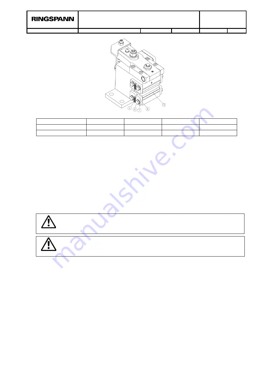
After replacing the brake pads, you have to adjust the air gap between the brake disc and the
brake pad. See the first steps in this chapter. After replacing the brake pads remember the chap-
ter 8.5. The entire surface of both brake pads must be in contact with the brake disc in order to
achieve the optimum braking effect. The brake pads must also be heated briefly to approx.
200°C. Therefore, multiple brief braking operations under low spring force and rotating brake disc
are required to heat the brake pads.
12. Accessories: switches
for brake closed, brake open and brake pad wear adjustment
Necessary (Option)
12.1 Installing and connecting the inductive proximity switches for brake closed, brake open and
brake pad wear adjustment necessary
Danger to life and limb!
The inductive proximity switch may be installed and/or replaced only when the
equipment system and/or working machine is at a complete standstill!
Danger!
When switching the brake, the lever Pos. 29 and the spring compressor Pos. 27
will move very fast.
You have to go through chapter 8 first, before you can assemble the inductive proximity switch.
The assembly of the inductive proximity switch is only possible after the brake is assembled and
the air gap between brake pad and brake disc is set correctly (see chapter 8 and 9). To indicate
„Brake open“, „Brake closed“ or “Brake pad adjustment necessary” a inductive proximity switch for
each request is to assemble. The inductive proximity switch is part of the sensor kit and supplied
loose as accessory. The sensor kit consists of an inductive proximity switch with two fastening
nuts, a fastening sheet metal and fastening screws and washers. On the brake housing you can
find threads to fasten the fastening sheet metal (see Fig. 12.1). On the metal sheet you have dif-
ferent assembling possibilities for “Brake open”, “Brake closed” and “Brake pad wear adjustment
necessary” (see Fig. 12.2). You always get a “high-signal” for each brake status. With one sensor
kit you can detect only one brake status, for further signals you have to order another proximity
switch in NC or NO version (see figure 12.2; 12.3 and 12.4). For sensor kits with more than one
sensor or for special requirements, such as other voltage ranges or low temperatures below -
25°C, please contact RINGSPANN.
Sensor kit:
Fig. 11.1


