


Installation and opreating instructios for tor-
sionally stiff gear couplings
RDZ…DTO/…DFO
E 06.705
As of: 12.08.2020
Version: 02
Signed: SCCE
Checked: SCHW
No. of pages: 21 Page: 10
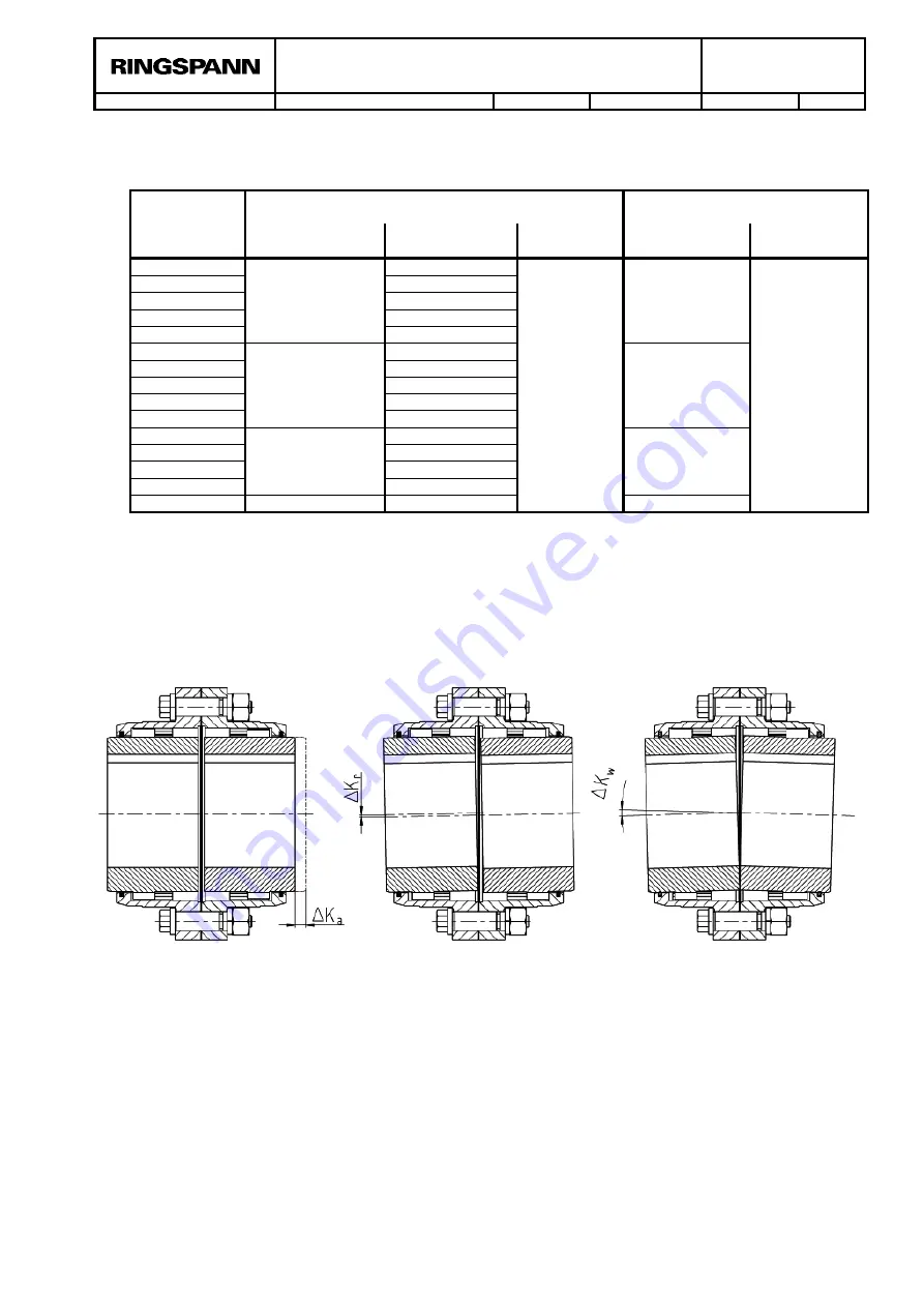
7.2. Permissible misalignments
Size
Max. permissible misalignments
RD
Z … DTO
Max. permissible misalignments
RD
Z … DFO
Axial ∆K
a
[inch]
Radial ∆K
r
[inch]
Angular
∆K
w
[◦]
Axial ∆K
a
[inch]
Angular
∆K
w
[◦]
0010
± 0.020
0.020
1.5
± 0.020
0.75
0015
0.031
0020
0.039
0025
0.047
0030
0.055
0035
± 0.039
0.067
± 0.039
0040
0.079
0045
0.083
0050
0.102
0055
0.114
0060
± 0.079
0.126
± 0.079
0070
0.146
0080
0.165
0090
0.189
0100
±0.118
0.217
±0.118
Table 7.2: Maximum permissible misalignments
The maximum permissible misalignment values (table 7.2) must be adhered to and may not oc-
cur at the same time. In the event of the simultaneous occurrence of radial and angular offset,
misalignments need to be calculated percentage-wise (see figure 7.2). If not observed, damage
to the coupling may result.
Figure 7.2: Misalignment types
The figure 7.2 shows the relationship for radial (K
r
) and angular misalignments (K
w
) occurring at
the same time:
Angular misalignment
Radial misalignment
Axial misalignment


