


Installation and opreating instructios for tor-
sionally stiff gear couplings
RDZ…DTO/…DFO
E 06.705
As of: 12.08.2020
Version: 02
Signed: SCCE
Checked: SCHW
No. of pages: 21 Page: 12
Size
RD
Z … DTO
RD
Z … DFO
Bore d1/d2 [inch]
Bore d1 [in]
Bore d2 [inch]
min.
max.
min.
max.
min.
max.
0010
0.59
1.88
0.59
1.88
0.59
2.38
0015
0.83
2.36
0.83
2.36
0.83
2.94
0020
1.10
2.84
1.10
2.84
1.10
3.63
0025
1.26
3.54
1.26
3.54
1.26
4.38
0030
1.50
4.13
1.50
4.13
1.50
5.13
0035
1.50
4.92
1.50
4.92
1.50
5.88
0040
1.50
5.71
1.50
5.71
1.50
7.25
0045
2.05
6.75
2.05
6.75
2.05
8.13
0050
2.80
7.38
2.80
7.38
2.80
9.00
0055
2.76
8.25
2.76
8.25
2.76
10.00
0060
4.33
9.13
4.33
9.13
4.33
11.00
0070
4.33
10.88
4.33
10.88
4.33
13.00
0080
4.33
13.19
4.33
13.19
4.33
13.09
0090
5.91
14.57
5.91
14.57
5.91
15.03
0100
6.30
15.94
6.30
15.94
6.30
16.03
Table 7.3: Permissible bore diameter
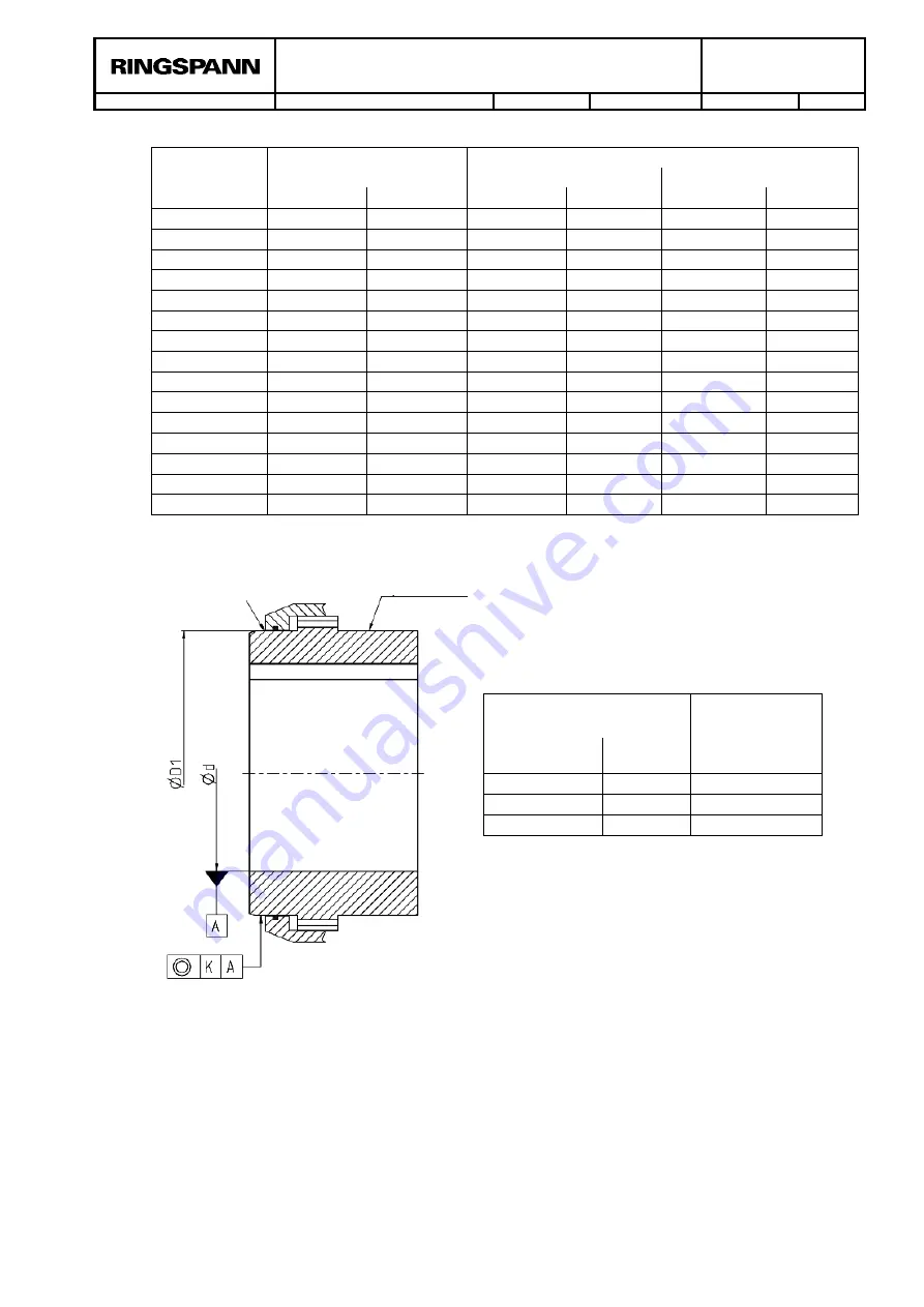
Figure 7.3: Specifications for the form and positional tolerance of the bore
The design and inspection of the keyway connection falls to the operator and is his responsi-
bility.
The gear couplings in the catalogue are designed with bore tolerance and keyway tolerance
per AGMA 9002-C14
.
Deviating fits are possible and should be communicated to RING-
SPANN as part of any query.
Diameter D1
[inch]
Max.
permissible
concentricity
[inch ]
from
to
0.3937
7.0866
0.0020
7.0866
15.7480
0.0035
15.7480
24.8032
0.0043
Sealing surface
Clamping surface


