17
Gas pressure setting
1. Attach pressure gauge to burner test point.
2. Turn on the gas and power supplies.
3.
If remote controllers are fitted, turn the unit ON at the controller and select
a maximum delivery temperature.
4.
Open hot water taps fully to reach maximum flow rate—ensure building
occupants do not have access to the hot water outlets during this
procedure.
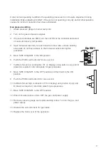
5. Move SW8 of DipSW1 to the ON position.
6. Push the PCB board button
A
for one second.
7. Calibrate forced low combustion (FL on display) using button A (up) and B
(down) as required, refer data plate for gas pressures.
8. Move SW8 of DipSW1 to the OFF position and then back to the ON
position.
9. Push the PCB board button B for one second.
10. Calibrate forced high combustion (FH on display) using button A (up) and
B (down) as required, refer data plate for gas pressures.
11. Move SW8 of DipSW1 to the OFF position.
12. Close hot water taps and turn OFF the gas, and power supply.
13. Remove pressure gauge and replace sealing screw. Turn on the gas, and
power supply.
14. Operate the unit and check for gas leaks.
15. Replace the front cover of the appliance.
5
6
7
8
ON
DipSW1
A
B
Under normal operating conditions the operating pressures do not require adjustment during
installation. Make adjustments ONLY if the unit is not operating correctly and all other possible
causes for incorrect operation have been eliminated.
Summary of Contents for A28i
Page 19: ......


