49
Design indication
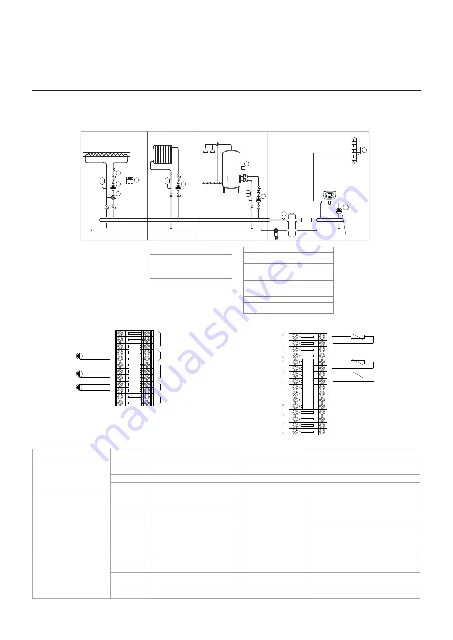
Indicative diagrams of operation
Pos. Description
A
Thermal generator (aiM)
Circ.
0
A
2
External temperature sensor
Accumulation temperature sensor
B
3
DHW circuit pump
B
6
Direct circuit pump
C
6
Heat production circuit
Production circuit A.C.S.
RC circuit - Direct
A
B
C
A
3
Flow temperature sensor
D
2
5
6
D
D
Contact temperature sensor
Mixing valve
Mixed circuit pump
RC circuit - Mixed n ° 1 (MIX)
D
D
External expansion module
4
A
B
A2
B3
B6
A3
INAIL
C
C6
D
D6
D5
D2
D4
PE
P
E
External boiler pump
05 - SINGLE GENERATOR - DIRECT CIRCUIT, MIXED CIRCUIT AND BOILER LOAD MANAGEMENT
Hydraulic scheme
Wiring diagram
SIG
N
A
L
LIN
E T
ER
M
IN
A
L
1
2
3
4
5
6
7
8
9
10
11
1
2
1
2
3
4
5
6
7
8
9
10
11
1
2
13
1
4
1
5
16
1
7
18
1
9
2
0
21
22
23
2
4
25
26
27
2
8
13
1
4
1
5
16
1
7
1
8
19
2
0
21
22
23
24
2
5
26
27
2
8
POWER SUPPLY
230V
HEATING CIRCUIT
PUMP(QX2)
DHW PUMP (QX3)
BOILER PUMP
HIGH EFFICIENCY (QX1)
MODULATING BOILER PUMP
CASCADE SENSOR (BX1)
DHW SENSOR (B3 / B38)
OUTSIDE TEMPERATURE
SENSOR (B9)
DIGITAL INPUT
(Room thermostat)
ROOM UNIT
ANALOG SENSOR
MODULATING PUMP SENSOR
PE
C6
A2
B6
A3
B3
ζ
ζ
ζ
Electronic programming
Description
Parameter
Selection
Standard Value
Value to set
Heating circuit 1
710
Comfort setpoint
20°C
Comfort setpoint
712
Reduced setpoint
16°C
Reduced setpoint
720
Heating curve slope
1,5
Heating curve slope
741
Flow temp setpoint max
80°C
Flow temp setpoint max
Domestic Hot Water
(DHW)
1610
Nominal setpoint
55°C
Nominal setpoint
1640
Legionella function
Recurring
Legionella function
1641
Legionella funct periodically
3 days
Legionella funct periodically
1642
Legionella funct weekday
Sunday
Legionella funct weekday
1644
Legionella funct time
03:00
Legionella funct time
1645
Legionella funct setpoint
65
Legionella funct setpoint
1646
Legionella funct duration
30 min
Legionella funct duration
Configuration
5715
Heating circuit 2
Off
Heating circuit 2
5890
Relay output QX1
-
Relay output QX1
5891
Relay output QX2
-
Relay output QX2
5892
Relay output QX3
-
Relay output QX3
5930
Sensor input BX1
Sensor input BX1
5931
Sensor input BX2
Sensor input BX2
Summary of Contents for aiM 115
Page 1: ...Modular boilers User and installation manual Indoor models aiM 65 aiM 115 aiM 85 aiM 150 ...
Page 17: ...13 Technical data Dimensions FRONT VIEW REAR VIEW TOP VIEW BOTTOM VIEW HEIGHT DEPTH ...
Page 65: ......
Page 66: ...Via Liguria 37 41012 Carpi Modena Tel 059 622 9248 e mail info rinnai it rinnai it 200626 ...


