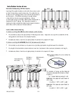
background image


28 

Rinnai CVent 

Options for Combustion Air Vent: 

• 

For extended Intake pipe runs, PVC can be used between the Intake Header and Termination. 

• 

Use the PVC adapter (described below) when transitioning from the 

PPTL/PPS 

intake header to the stainless 

steel Combustion Air Termination.  


• 

Combustion Air PVC Adapter Kit (Part #: 790037) includes both a transition from the 8” (200mm) PP header 
to 8” PVC and an 8”PVC to 8” (200mm) termination 


• 

Fasten, secure, and support all vent materials using manufacturer and industry standards to avoid potential 
intake air leaks or blockage.  Support horizontal vent runs a minimum of every 4 feet and all vertical vent 
runs a minimum of every 6 feet. 

The materials described below can only be used on the combustion air vent.  The Ubbink 
Polypropylene CVent can be used on both the combustion air and exhaust. Field supplied 
PVC material can only be used on the combustion air side and 

MUST NOT

 be used for 

the exhaust. 


WARNING


Approval Codes for In-
stallation  

Item Description 

Flue Material 

United States 

Plastic Vent and/or 

combustion air  

components 

PVC  Schedule 40 

ANSI/ASTM D1785 

PVC - DWV 

ANSI/ASTM D2665 

CPVC Schedule 40 

ANSI/ASTM F441 

Plastic pipe cement 

and primer  

PVC 

ANSI/ASTM D2564 

CPVC 

ANSI/ASTM F493 

FIELD 

SUPPLIED 

PVC PIPE 

Plastic pipe 

cement and 

primer  

PVC to TERMINATION ADAPTER: 
8”PVC to 8” (200mm) termination


PP to PVC ADAPTER: 
8” (200mm) PP header to 8” PVC 


Summary of Contents for c199i

Page 1: ...Do not touch any electrical switch do not use any phone in your building Immediately call your gas supplier from a neighbor s phone Follow the gas supplier s instructions If you cannot reach your gas supplier call the fire department Installation and service must be performed by a licensed professional If the information in these instructions is not followed exactly a fire or explosion may result ...

Page 2: ...ng Rinnai tankless condensing water heaters only RU98i REU KB3237FFUD US RUC98i REU KBD3237FFUD US and C199i REU KBD3237FFUDC US Installer Qualifications 2 Description 2 Model Applicability 2 Safety Symbols 3 Warranty and Liability Exclusions 3 Specifications 3 High Altitude Installation 4 Parts Kits 5 Sample Roof Installation 13 Sample Horizontal Termination Installation 14 Sample Vertical Termin...

Page 3: ...the unit or to the individual components Installation of components which are not part of the Cvent system Subsequent damage which occurred through further use of the Cvent system despite known defects Intentional damage Force Majeure Warranty and Liability Exclusions Specifications Number of water heaters Percent De rated Total Btu Rate Btu at Minimum Rate without MSB Btu at Minimum Rate with MSB...

Page 4: ...perly installed and setup for the altitude that they will be operating at For information on how to adjust altitude settings reference the respective In stallation and Operation Manual for the RU98i REU KB3237FFUD US RUC98i REU KBD3237FFUD US and C199i REU KBD3237FFUDC US tankless water heaters Water heaters using CVent at altitudes over 2 000ft will automatically de rate according to the table be...

Page 5: ...der kit CV8BB7USDV CV8BB7CADV 8 back to back 8 unit header kit CV8BB8USDV CV8BB8CADV 8 in line 3 unit header kit CV8IL3USDV CV8IL3CADV 8 in line 4 unit header kit CV8IL4USDV CV8IL4CADV 8 in line 5 unit header kit CV8IL5USDV CV8IL5CADV 8 in line 6 unit header kit CV8IL6USDV CV8IL6CADV 8 in line 7 unit header kit CV8IL7USDV CV8IL7CADV 8 in line 8 unit header kit CV8IL8USDV CV8IL8CADV Back to Back Co...

Page 6: ...8BB6CARA 8 back to back 7 unit header kit CV8BB7USRA CV8BB7CARA 8 back to back 8 unit header kit CV8BB8USRA CV8BB8CARA 8 in line 3 unit header kit CV8IL3USRA CV8IL3CARA 8 in line 4 unit header kit CV8IL4USRA CV8IL4CARA 8 in line 5 unit header kit CV8IL5USRA CV8IL5CARA 8 in line 6 unit header kit CV8IL6USRA CV8IL6CARA 8 in line 7 unit header kit CV8IL7USRA CV8IL7CARA 8 in line 8 unit header kit CV8...

Page 7: ...AIN HOSE AND CLAMPS 790049 NA 6 1 UBBINK INSTALLATION INSTRUCTION NA NA 7 1 CENTROCERIN LUBRICANT NA NA NO QTY DESCRIPTION PPTL PART S PPS PART S 1 1 CVENT COLLECTOR 1 CONNECTION D8 X L20 X D4 Exhaust 790040 NA 2 1 CVENT ELBOW D4 X 87 WITH CLEANOUT 790039 NA 3 1 CVENT EXTENSION D4 X L18 790035 NA 4 1 CVENT APPLIANCE ADAPTER WITH CHECK VALVE AND HOSE TRAP 790038 NA 5 1 CVENT COMB AIR COLLECTOR 1 CO...

Page 8: ...ECTION D8 X L20 790041 NA 2 2 CVENT ELBOW D4 X 87 WITH CLEANOUT 790039 NA 3 2 CVENT EXTENSION D4 X L18 790035 NA 4 2 CVENT APPLIANCE ADAPTER WITH CHECK VALVE AND 790038 NA 5 1 CVENT COMB AIR COLLECTOR 2 CONNECTION 780045 NA 6 2 CVENT COMB AIR FLEX FITTING D3 780050 NA 7 1 CENTROCERIN LUBRICANT NA NA 1 5 2 4 3 6 Ø4 Ø3 Ø4 Ø3 7 PPS kits and components are certified for use in Canada ...

Page 9: ... X D4 Exhaust 790040 NA 2 1 CVENT ELBOW D4 X 87 WITH CLEANOUT 790039 NA 3 1 CVENT EXTENSION D4 X L18 790035 NA 4 1 CVENT APPLIANCE ADAPTER ROOM AIR CHECK VALVE HOSE TRAP NA NA 5 1 CENTROCERIN LUBRICANT NA NA 5 4 1 3 2 4 NO QTY DESCRIPTION PPTL PART S PPS PART S 1 1 CVENT ENDPIECE EXHAUST W CLEANOUT CONDENSATE DRAIN 32mm 790042 NA 2 1 CVENT CONDENSATE TRAP 32mm Connection 790048 NA 3 1 CVENT DRAIN ...

Page 10: ...nt Applications NO QTY DESCRIPTION PPTL PART S PPS PART S 1 1 CVENT COLLECTOR 2 CONNECTION D8 X L20 790041 NA 2 2 CVENT ELBOW D4 X 87 WITH CLEANOUT 790039 NA 3 2 CVENT EXTENSION D4 X L18 790035 NA 4 1 CVENT APPLIANCE ADAPTER ROOM AIR CHECK VALVE HOSE TRAP NA NA 5 1 CENTROCERIN LUBRICANT NA NA 1 2 3 Ø4 Ø4 5 4 1 3 2 4 PPS kits and components are certified for use in Canada ...

Page 11: ...90004 for use with PPtl and PPS material Centrocerin lubricant Material Stainless Steel Cvent 8 in Roof Termination Kit 790057 791007PPS can be used as Intake or Exhaust Centrocerin Lubricant CVent 8 in Roof Termination Outer shell available in PPtl or PPS If roof termination is being used as intake the assembly must include the intake rain cap ...

Page 12: ...Condensate Trap 790032 CVent Elbow D8x45 degree 790022 791002PPS Qty 2 CVent Elbow D8x90 degree 790023 791003PPS CVent Extension D8xL18 790020 D8xL39 790021 791001PPS D8xL78 790052 791006PPS CVent Elbow D8x90 degree Vertical Support 790029 CVent 8 in Bracket 790024 CVent 8in Vent Distancer 790031 Combustion Air PVC Adapter Kit 780037 CVent 8in Vent Rain Cap Intake 780053 CVent Extension D4xL18 790...

Page 13: ... flashing 790003 Field Supplied PVC Components Field Supplied 8 PVC Flashing CVent 8in Vent Rain Cap Exhaust 790034 OPTIONAL Vent termination per ANSI Z223 1 NFPA 54 For clearances not specified in ANSI Z223 1 NFPA 54 clearances are in accordance with local installation codes and the requirements of the gas supplier Intake Exhaust ...

Page 14: ...stion Air PVC Adapter Kit Part Number 790023 CVent Elbow D8 x 90 Part Number 790005 CVent Starter Kit Part Number 790004 Wall Termination Kit Combustion Air Exhaust Field Supplied PVC Components Field Supplied PVC Components Sample Horizontal Termination Assembly Complete Header Kit Pictured U S CV8BB8USDV Canada CV8BB8CADV ...

Page 15: ...Z223 1 NFPA 54 For clearances not specified in ANSI Z223 1 NFPA 54 clearances are in accordance with local installation codes and the requirements of the gas supplier Part Number 790023 CVent Elbow D8 x 90 Part Number 790005 CVent Starter Kit Part Number 790060 CVent Back 2 Back Kit Part Number 790057 CVent 8 in Roof Termination Part Number 790020 790021 CVent Extension CVENT APPLIANCE ADAPTER WIT...

Page 16: ...rt horizontal vent runs a minimum of every four feet and all vertical vent runs a minimum of every six feet Venting should be as direct as possible with a minimum number of pipe fittings Vent connections must be firmly pressed together so that the gaskets form an air tight seal Install an appliance adapter which contains a check valve onto each water heater Use only the check valve specified in th...

Page 17: ... C199i REU KBD3237FFUDC US RUC98i REU KBD3237FFUD RU98i REU KB3237FFUD US 8 15 41 41 Vertical or Horizontal Parallel Pipe Configuration Same Pressure Zone Face the Same Direction Page 23 2 to 7 100 100 Vertical Termination There should be a minimum of 36 between exhaust and intake terminations CVent Termination Clearances Clearances of Brackets All supports such as wall brackets on the external fa...

Page 18: ...aust CVents There should be a minimum of 36 between exhaust terminations in multiple common vent installations The vent exhaust combustion air terminations to be as specified in table in Maximum Equivalent Vent Length Section above model specific NOTE During colder weather when the exhaust temperature is much hotter than the outside air the exhaust fumes condense producing water vapor As a result ...

Page 19: ... ammonia cat litter aerosol sprays cleaning solvents varnish paint and air fresheners Do not store these products or similar products in the vicinity of the water heater system Unconfined Space An unconfined space is defined in National Fuel Gas Code ANSI Z223 1 NFPA 54 as a space whose volume is not less than 50 cubic feet per 1000 Btu hr 4 8 m3 per kW per hour of the aggregate input rating of al...

Page 20: ...be positioned in confined spaces The upper shall be within 12 of the top of the confined space and the lower opening shall be within 12 of the bottom of the confined space Openings must be positioned as to never be obstructed Using Outdoor Air For Combustion Outdoor air can be provided to a confined space through two permanent openings one commenc ing within 12 in 300mm of the top and one commenci...

Page 21: ...ting of all appliances in the confined space Combustion air to the appliance can be provided from a well ventilated attic or crawl space WARNING TO PREVENT POSSIBLE PERSONAL INJURY OR DEATH DUE TO ASPHYXIATION COMMON VENTING WITH OTHER MANUFACTURER S INDUCED DRAFT APPLIANCES IS NOT ALLOWED Verify proper clearances around the vents Ensure that the Combustion Air Requirements are followed that will ...

Page 22: ...fer to Common Vent Manual In common vent configurations utilizing different pressure zones roof exhaust with sidewall inlet or room air exhaust MUST terminate vertically ATTENTION Option 1 Vertical Vent and Horizontal Air Intake Exhaust Combustion Air Option 2 Room air for combustion must terminate vertically Exhaust Back to Back Installation Option 1 Parallel Termination Exhaust Combustion Air Co...

Page 23: ...ns US Installations A Clearance above grade veranda porch deck or balcony 12 inches 30 cm 12 inches 30 cm B Clearance to window or door that may be opened 36 inches 91 cm 12 inches 30 cm C Clearance to permanently closed window D Vertical clearance to ventilated soffit located above the terminal within a horizontal distance of 2 feet 61 cm from the center line of the terminal E Clearance to unvent...

Page 24: ... Clearance to permanently closed window D Vertical clearance to ventilated soffit located above the terminal within a horizontal distance of 2 feet 61 cm from the center line of the terminal E Clearance to unventilated soffit F Clearance to outside corner G Clearance to inside corner H Clearance to each side of center line extended above meter regulator assembly 3 feet 91 cm within a height 15 fee...

Page 25: ... could create a nuisance or hazard or cause property damage or Where condensate or vapor could cause damage or could be detrimental to the operation of regulators relief valves or other equipment Important considerations for locating vent termination under a soffit ventilated or unventilated or eave vent or to a deck or porch Do not install vent termination under a soffit vent such that exhaust ca...

Page 26: ...side to front to top to floor ground Maintenance Clearances Back to Back Configuration In Line Configuration Follow the recommended minimum service clearances below for maintenance access to the header above the water heater If the vent system is to be enclosed it is suggested that the design of the enclosure shall permit inspection of the vent system The design of such enclosure shall be deemed a...

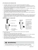
Page 27: ...ot cut or modify the elbow Cleanout cap should remain accessible for periodic inspection and access for service when needed After combustion air and exhaust vent components are appropriately positioned securely fasten the CVent Appliance Adapter with Check Valve and Trap to the top of the water heater with a self tapping screw Connect the combustion air opening of the appliance adapter to one end ...

Page 28: ...imum of every 4 feet and all vertical vent runs a minimum of every 6 feet The materials described below can only be used on the combustion air vent The Ubbink Polypropylene CVent can be used on both the combustion air and exhaust Field supplied PVC material can only be used on the combustion air side and MUST NOT be used for the exhaust WARNING Approval Codes for In stallation Item Description Flu...

Page 29: ... Room air configurations follow the same instructions excluding information regarding air intake The installation area should be measured to make sure that adequate space is available to install the water heaters and venting system NOTE Dimensions above are used in all back to back configurations Note If water heaters are mounted directly on a wall air intake piping will need to be in front of the...

Page 30: ...al codes Inspectors can reject the installation if the rating plate cannot be seen for all water heaters D4 Extension Pieces must be cut appropriately to maintain the required 3 slope If common venting with GREATER than 20 5 between water heaters The installer must purchase a vent extension cut to the appropriate length between the collectors The length of each additional vent extension must be co...

Page 31: ...p prevent corrosion of the drain and public sewer system Ensure that the condensate drain does not freeze Long Vent Run or Restricted Rise Applicable where allowed by code An inverter coupling kit with a condensate trap is available to reduce the rise of the exhaust vent A diagram of its installation is shown below The male male and female female connectors must be used so that the venting is orie...

Page 32: ... the check valve out For smaller particles under 1mm we advise to use a sufficient amount of luke warm water to flush the adapter Do not use detergents or solvents for cleaning the check valve When applicable the small check valve can be removed and re installed for inspection by pulling it out of position We do not advise to do this frequently When re installed the check valve must be inspected a...

Page 33: ...anty The installation must conform with local codes or in the absence of local codes with the National Fuel Gas Code ANSI Z223 1 NFPA 54 or the Natural Gas and Propane Installation Code CSA B149 1 Inform the consumer if the isolation valves are not installed or if a water softening system is not installed Verify that only models RU98i REU KB3237FFUD US RUC98i REU KBD3237FFUD US or C199i REU KBD323...

Page 34: ...the following reasons Use of the CVent system not in accordance with the regulations Improper assembly and incorrect operation Faulty maintenance Non compliance with the assembly and operating instructions Non approved structural changes to the unit or to the individual components Installation of components which are not part of the CVent system Subsequent damage which occurred through further use...

Page 35: ... Valves 41 A12 Clearances of brackets 41 A13 Inspection after assembly 41 A14 Application manufacturer s Information 42 A1 Preface These installation instructions were compiled in accordance with the current state of technology and with the greatest care They serve as a general guideline for the construction and operation of the CVent Common Vent System as supplied by Rinnai US manufactured by Ubb...

Page 36: ...industrial safety regulations These must especially be complied with unconditionally and at any time when working on roofs and fa çades A4 Transport and storage When transporting CVent Common Vent System components the following points must be complied with Transport CVent Common Vent System components in a clean dry environment and only in its original packaging If stored or transported at temper...

Page 37: ...eal Direction and Assembly of Seals Seals are pre assembled in the vent components If a seal is missing or dam aged this component should not be used or an appropriate seal must be in stalled Use ONLY CVent original seals NEVER use fabricated or non CVent seals Use only the appropriate nominal width and diameter seals Confirm seal is installed in the appropriate direct see figure Seal and Seal Cha...

Page 38: ...ming 3rd party condensate valves or a hose loop DO need priming to be effective Do not fire the appliances before the condensate traps are inspected and or primed otherwise flue gasses can escape form the common vent system All subsequent drains must have a minimum diameter of 1 2 12mm and must be protected if applicable from freezing A8 Instructions to be complied with When assembling the CVent C...

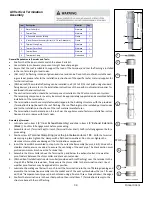
Page 39: ...Cap to item 5 Terminal Outer Shell Confirm full engagement before proceeding 3 Position item 4 Terminal Clamp Ring over the joint between items 1 5 With the terminal clamp ring in place tighten the clamps with a flathead screwdriver Do not over tighten the clamps as this could cause damage of the termination components 4 Insert the items 2 3 assembled in step 1 into the outer shell assembly items ...

Page 40: ...bes are connected to a drain and comply with local code All condensate traps have been primed There are no obstructions in the combustion air or exhaust vent runs Both intake and exhaust terminations are appropriately positioned and comply with the manu facturers installation instructions and local codes The CVent Common Vent System Installation Instructions and the Appliance Installation In struc...

Page 41: ...ionality of the valves A12 Clearances of brackets All supports such as e g wall brackets on the external façade or spacer blocks in a shaft must be assembled in a maximum distance of 6ft 2m Where there is an bend additional spacer blocks or wall brackets can be planned before and after the bend depending on the local situation A13 Inspection after assembly After assembly of a system chimney the fo...

Page 42: ...w by the installer after release of the system Installation date of the system chimney Number of entries appliances Nominal diameter of the selected system chimney Constructor of the chimney with full name Stamp legible and with signature OEM Manufacturer identification Ubbink Centrotherm Centrotec Sustainable AG Verhuellweg 9 6984AA Doesburg The Netherlands Mail rolux ubbink nl YYYY MM DD Name St...

Page 43: ...43 Rinnai CVent NOTES ...

Page 44: ...ur électrique N utilisez aucun téléphone dans votre bâtiment Appelez immédiatement votre fournisseur de gaz depuis un téléphone du voisinage Suivez les instructions qu il vous donnera Si vous ne pouvez pas joindre votre fournisseur de gaz appelez les pompiers Installation et interventions de service doivent être effectuées par un professionnel agréé Si les informations de ces instructions ne sont ...

Page 45: ...au à condensation sans réservoir Rinnai suivants RU98i REU KB3237FFUD US RUC98i REU KBD3237FFUD US et C199i REU KBD3237FFUDC US Qualifications de l installateur 45 Description 45 Applicabilité aux modèles 45 Symboles de sécurité 46 Exclusions de garantie et de responsabilité 46 Spécifications 46 Installations à forte altitude 47 Pièces Kits 48 Exemple d installation sur toit 56 Exemple d installat...

Page 46: ...ble ou sur des composants individuels Installation de composants qui ne font pas partie du système CVent Dommages ultérieurs provoqués par la continuation d utilisation du système CVent malgré la connaissance de l existence de défauts Dommages intentionnels Cas de force majeure Exclusions de garantie et de responsabilité Spécifications Nombre de chauffe eau Pourcentage de réduction Puissance total...

Page 47: ...e eau sont correctement installés et configurés pour l altitude à laquelle ils vont fonctionner Pour avoir des informations sur la façon de configurer les chauffe eau sans réservoir selon l altitude référez vous aux manuels d installation et d utilisation des modèles RU98i REU KB3237FFUD US RUC98i REU KBD3237FFUD US et C199i REU KBD3237FFUDC US Les chauffe eau utilisant CVent à des altitudes dépas...

Page 48: ...de collecteur commun pour 8 en 8 dos à dos CV8BB8USDV CV8BB8CADV Kit de collecteur commun pour 3 en 8 en ligne CV8IL3USDV CV8IL3CADV Kit de collecteur commun pour 4 en 8 en ligne CV8IL4USDV CV8IL4CADV Kit de collecteur commun pour 5 en 8 en ligne CV8IL5USDV CV8IL5CADV Kit de collecteur commun pour 6 en 8 en ligne CV8IL6USDV CV8IL6CADV Kit de collecteur commun pour 7 en 8 en ligne CV8IL7USDV CV8IL7...

Page 49: ...pour 7 en 8 dos à dos CV8BB7USRA CV8BB7CARA Kit de collecteur commun pour 8 en 8 dos à dos CV8BB8USRA CV8BB8CARA Kit de collecteur commun pour 3 en 8 en ligne CV8IL3USRA CV8IL3CARA Kit de collecteur commun pour 4 en 8 en ligne CV8IL4USRA CV8IL4CARA Kit de collecteur commun pour 5 en 8 en ligne CV8IL5USRA CV8IL5CARA Kit de collecteur commun pour 6 en 8 en ligne CV8IL6USRA CV8IL6CARA Kit de collecte...

Page 50: ...T COLLIERS DE CVENT 790049 ND 6 1 INSTRUCTIONS D INSTALLATION D UBBINK ND ND 7 1 LUBRIFIANT CENTROCERIN ND ND N Qté DESCRIPTION Réf pièce PPTL Réf pièce PPS 1 1 COLLECTEUR DE CVENT 1 CONNEXION D8 X L20 X D4 Évacuation 790040 ND 2 1 COUDE DE CVENT D4 X 87 AVEC NETTOYAGE 790039 ND 3 1 EXTENSION DE CVENT D4 X L18 790035 ND 4 1 ADAPTATEUR DE CVENT SUR CHAUFFE EAU AVEC CLAPET ANTI RETOUR ET PIÈGE À TUY...

Page 51: ...VENT D4 X 87 AVEC NETTOYAGE 790039 ND 3 2 EXTENSION DE CVENT D4 X L18 790035 ND 4 2 ADAPTATEUR DE CVENT SUR CHAUFFE EAU AVEC CLA PET ANTI RETOUR ET PIÈGE À TUYAU 790038 ND 5 1 COLLECTEUR D AIR DE COMBUSTION DE CVENT 2 CON NEXIONS D8 X L20 X D3 780045 ND 6 2 RACCORD FLEXIBLE D AIR DE COMBUSTION POUR CVENT D3 780050 ND 7 1 LUBRIFIANT CENTROCERIN ND ND 1 5 2 4 3 6 Ø4 Ø3 Ø4 Ø3 7 Les kits et composants...

Page 52: ...NEXION D8 X L20 X D4 Évacuation 790040 ND 2 1 COUDE DE CVENT D4 X 87 AVEC NETTOYAGE 790039 ND 3 1 EXTENSION DE CVENT D4 X L18 790035 ND 4 1 ADAPTATEUR DE CVENT SUR CHAUFFE EAU AVEC CLAPET ANTI RETOUR ET PIÈGE À TUYAU ND ND 5 1 LUBRIFIANT CENTROCERIN ND ND 5 4 1 3 2 4 N Qté DESCRIPTION Réf pièce PPTL Réf pièce PPS 1 1 PIÈCE D EXTRÉMITÉ DE CVENT ÉVACUATION AVEC DRAIN DE NETTOYAGE ET DE CONDENSATS 32...

Page 53: ...lation commune N Qté DESCRIPTION Réf pièce PPTL Réf pièce PPS 1 1 COLLECTEUR DE CVENT 2 CONNEXIONS D8 X L20 790041 ND 2 2 COUDE DE CVENT D4 X 87 AVEC NETTOYAGE 790039 ND 3 2 EXTENSION DE CVENT D4 X L18 790035 ND 4 1 ADAPTATEUR DE CVENT SUR CHAUFFE EAU AIR DE LA PIÈCE AVEC CLAPET ANTI RETOUR ET PIÈGE À TUYAU ND ND 5 1 LUBRIFIANT CENTROCERIN ND ND 1 2 3 Ø4 Ø4 5 4 1 3 2 4 Les kits et composants en PP...

Page 54: ...e utilisation avec matériau PPtl et PPS Lubrifiant Centrocerin Matériau Acier inox Kit de terminaison de toit pour CVent 8 790057 791007PPS peut s utiliser comme admission ou évacuation Lubrifiant Centrocerin Terminaison de toit pour CVent 8 Enveloppe externe Disponible en PPtl ou PPS Si une terminaison de toit est utilisée comme admission l ensemble doit inclure le capuchon pare pluie ...

Page 55: ... piège à condensats Réf 790032 Coude CVent D8x45 Réf 790022 791002PPS Coude CVent D8x90 Réf 790023 791003PPS Extension CVent D8xL18 Réf 790020 D8xL39 Réf 790021 791001PPS D8xL78 Réf 790052 791006PPS Coude CVent D8x90 Support vertical Réf 790029 Support CVent 8 Réf 790024 Écarteur de ventilation CVent 8 Réf 790031 Adaptateur PCV d air de combustion Réf 780037 Capuchon CVent 8 pare pluie admission R...

Page 56: ...osants PCV de fourniture locale Solin PCV pour 8 de fourniture locale Capuchon CVent 8 pare pluie évacuation Réf 790034 OPTIONNEL Terminaison de ventilation conforme ANSI Z223 1 NFPA 54 Pour des dégagements non spécifiés dans ANSI Z223 1 NFPA 54 ils devront être en conformité avec les normes locales d installation et les exigences du fournisseur de gaz Admission Évacuation ...

Page 57: ...ustion N de pièce 790023 Coude CVent D8 x 90 N de pièce 790005 Kit de démarrage CVent N de pièce 790004 Kit de terminaison murale Air et évacuation de combustion Composants PCV de fourniture locale Composants PCV de fourniture locale Exemple d installation de terminaison horizontale Kit de collecteur complet illustré USA CV8BB8USDV Canada CV8BB8CADV ...

Page 58: ...orme ANSI Z223 1 NFPA 54 Pour des dégagements non spécifiés dans ANSI Z223 1 NFPA 54 ils devront être en conformité avec les normes lo cales d installation et les exigences du fournisseur de gaz N de pièce 790023 Coude CVent D8 x 90 N de pièce 790005 Kit de démarrage CVent N de pièce 790060 Kit CVent dos à dos N de pièce 790057 Terminaison de toit pour CVent 8 N de pièce 790020 790021 Extension CV...

Page 59: ...installant des supports selon les instructions du constructeur de la ventilation Supportez les tronçons horizontaux de ventilation au moins tous les 120 cm et tous ses tronçons verticaux au moins tous les 180 cm La ventilation doit être aussi directe que possible avec un minimum de raccords de tuyaux Les connexions de ventilation doivent être fermement pressées ensemble de façon à ce que les joint...

Page 60: ...fig à tuyaux parallèles zone de pression différente Page 23 7 80 80 2 à 6 100 100 C199i REU KBD3237FFUDC US RUC98i REU KBD3237FFUD RU98i REU KB3237FFUD US 8 15 41 41 Verticale ou horizontale Config à tuyaux parallèles même zone de pression et même orientation Page 23 2 à 7 100 100 Terminaison verticale Il doit y avoir au moins 36 91 cm entre les terminaisons d évacuation et d admission Dégagements...

Page 61: ...ventilations communes Les terminaisons de ventilation évacuation et admission d air de combustion doivent se conformer aux spécifications du tableau Longueur de ventilation maximâle équivalente qui précède spécifique par modèle REMARQUE Durant la saison la plus froide quand la température d évacuation est bien plus élevée que l air ambiant extérieur les fumées d échappement provoquent une condensa...

Page 62: ...De tels produits chimiques peuvent se trouver sans y être limité dans eau de javel ammoniac litière pour chat bombe aérosol solvants de nettoyage vernis peinture et assainisseurs d air Ne les entreposez pas ainsi que des produits similaires à proximité de ce système de chauffe eau Espace non confiné Un espace non confiné est défini dans la Norme américaine sur le gaz combustible ANSI Z223 1 NFPA 5...

Page 63: ... haut doit être à moins de 12 pouces 30 cm du plafond de l espace confiné et celle du bas à moins de 12 pouces 30 cm du plancher de l espace confiné Ces ouvertures doivent être orientées de façon à n être jamais obstruées Utilisation d air extérieur pour la combustion De l air extérieur peut être fourni à un espace confiné au travers de deux ouvertures permanentes l une commençant à moins de 12 po...

Page 64: ...i depuis des combles ou un vide sanitaire étant bien ventilés AVERTISSEMENT POUR ÉVITER LA POSSIBILITÉ DE BLESSURE INDIVIDUELLE POUVANT ÊTRE FATALE SUITE À UNE ASPHYXIE UNE VENTILATION COMMUNE AVEC DES APPAREILS À TIRAGE INDUIT D AUTRES CONSTRUCTEURS N EST PAS PERMISE Vérifiez que les dégagements sont corrects autour des ventilations Assurez vous que les besoins en air de combustion sont satisfait...

Page 65: ...ation commune Dans les configurations de ventilation commune avec zones de pression différentes évacuation par le toit admission par mur latéral ou air de la pièce l évacuation DOIT se terminer verticalement ATTENTION Option 1 Ventilation verticale et admission d air horizontale Évacuation Air de combustion Option 2 Air de la pièce pour la combustion la terminaison doit être verticale Évacuation I...

Page 66: ...du sol véranda porche plate forme ou balcon 12 po 30 cm 12 po 30 cm B Dégagement par rapport à porte ou fenêtre pouvant être ouverte 36 po 91 cm 12 po 30 cm C Dégagement par rapport à une fenêtre restant fermée en permanence D Dégagement vertical par rapport à un soffite ventilé situé au dessus de la terminaison à une distance horizontale de moins de 2 pieds 60 cm de l axe de cette terminaison E D...

Page 67: ...nt vertical par rapport à un soffite ventilé situé au dessus de la terminaison à une distance horizontale de moins de 2 pieds 60 cm de l axe de cette terminaison E Dégagement par rapport à un soffite non ventilé F Dégagement par rapport à un angle sortant G Dégagement par rapport à un angle rentrant H Dégagement par rapport à une ligne centrale prolongée au dessus de l ensemble de compteur régulat...

Page 68: ...éer une nuisance ou un risque ou provoquer des dégâts matériels Là où des condensats ou de la vapeur pourraient causer des dommages ou être néfastes au bon fonctionnement des régulateurs des robinets de purge ou à un autre équipement Importantes considérations pour situer la terminaison de ventilation sous un soffite ventilé ou non ou à évent d avant toit ou bien sous un platelage ou un porche N i...

Page 69: ...hauffe eau to side to front to top to floor ground Dégagements pour l entretien Configuration dos à dos Configuration en ligne Respectez les dégagements minimaux recommandés pour l entretien qui suivent pour les interventions de maintenance sur le collecteur au dessus des chauffe eau Si le système de ventilation doit être enfermé il est suggéré que la conception de son enveloppe permette son inspe...

Page 70: ...entilation n en soit pas affecté Installez les coudes avec capuchon de nettoyage manuel sur le tuyau d extension de diamètre 4 Ne coupez pas ou ne modifiez pas le coude Le capuchon pour nettoyage doit rester accessible pour de l inspection périodique et un accès de service quand c est nécessaire Une fois que les composants pour air de combustion et évacuation sont bien en place serrez bien l adapt...

Page 71: ...ons horizontaux de ventilation au moins tous les 120 cm et tous ses tronçons verticaux au moins tous les 180 cm Le matériau décrit ci après ne peut être utilisé que sur la ventilation d air de combustion Le CVent Ubbink en polypropylène peut être utilisé pour l air de combustion comme pour l évacuation Le matériau PCV de fourniture locale ne peut s utiliser que pour le côté admission d air de comb...

Page 72: ...ce on les mêmes instructions sauf en ce qui concerne leur admission d air La zone d installation doit être mesurée pour s assurer qu un espace adéquat est disponible pour la mise en place des chauffe eau et de leur système commun de ventilation REMARQUE Les dimensions ci dessus sont utilisées pour toutes les configurations dos à dos Remarque Si les chauffe eau sont montés directement sur un mur la...

Page 73: ... qui concerne les normes locales en vigueur Des inspecteurs peuvent rejeter l installation si la plaque signalétique de tous les chauffe eau n est pas visible Des pièces d extension D4 doivent être convenablement coupées pour maintenir la pente de 3 requise En cas de ventilation commune avec PLUS de 20 5 entre les chauffe eau L installateur doit acheter une extension de ventilation coupée à la bon...

Page 74: ...me public d égoûts Assurez vous que le drainage de condensats ne pourra pas geler Long trajet de ventilation ou pente restreinte applicable si la norme le permet Un kit de couplage d inverseur muni d un piège à condensats est disponible pour réduire la pente de la ventilation d évacua tion Un schéma de son installation est montré ci dessous Les connecteurs mâle mâle et femelle femelle doivent être...

Page 75: ...eillons d utiliser une quantité suffisante d eau tiède pour rincer l adaptateur N utilisez pas de détergents ou de solvants pour le nettoyage du clapet anti retour Quand c est nécessaire le petit clapet peut être sorti pour inspection en le tirant et remis en place ensuite Nous ne conseilons pas de le faire fréquemment Après sa remise en place il faut de nouveau inspecter le clapet pour vérifier s...

Page 76: ... en conformité avec les normes locales ou à défaut avec la norme américaine sur le gaz combustible ANSI Z223 1 NFPA 54 ou la norme canadienne sur les installations au gaz naturel et au propane CSA B149 1 Informez le client si des vannes d isolement ou un système d adoucissement de l eau ne sont pas installées Vérifiez que seuls des modèles RU98i REU KB3237FFUD US RUC98i REU KBD3237FFUD US ou C199i...

Page 77: ...isons Utilisation du système Cvent sans être en conformité avec les réglementations Montage inadéquat ou utilisation incorrecte Mauvais entretien Non respect des instructions de montage et d utilisation Changements structurels non permis sur l ensemble ou sur des composants individuels Installation de composants qui ne font pas partie du système Cvent Dommages ultérieurs provoqués par la continuat...

Page 78: ...ucteur sur l application 85 A1 Préface Ces instructions d installation ont été rassemblées en conformité avec le stade actuel de la technologie et avec le plus grand soin Elles servent comme guidage général pour la construction et la mise en fonctionnement du système de ventilation commune fourni par Rinnai US et fabriqué par Ubbink Si vous aviez des questions supplémentaires n hésitez pas à consu...

Page 79: ...iment les respecter de façon inconditionnelle et en permanence lors du travail sur toit et façades A4 Transport et entreposage Quand vous transportez les composants du système de ventilation commune CVent les points suivants sont à respecter Transportez les composants du système de ventilation commune CVent dans un environnement propre et sec et seule ment dans leur emballage d origine S ils ont é...

Page 80: ...chéité Les joints sont pré assemblés dans les composants de ventilation Si un joint est man quant ou endommagé ce composant ne doit pas être utilisé ou un joint approprié doit y être installé Utilisez SEULEMENT des joints CVent d origine N utilisez JAMAIS des joints in dustriels ou d une autre origine que CVent Les joints de remplacement devront avoir l épaisseur et le diamètre appropriés selon le...

Page 81: ...un diamètre d au moins 1 2 12mm et doivent être protégés s il y a un risque de gel A8 Instructions à respecter Quand vous assemblez les composants du système de ventilation commune CVent les points suivants sont à respecter Adaptation correcte des joints Utilisation complète de la profondeur d insertion des tuyaux et pièces préformées Le montage doit être réalisé avec une inclinaison d au moins 3 ...

Page 82: ...inuer 3 Positionnez la pièce 5 Bague de serrage de terminaison sur le joint entre les pièces 2 et 6 Une fois qu elle est en place serrez avec un tournevis à lame plate Ne serrez pas avec excès car cela pour rait endommager des composants de la terminaison 4 Insérez les pièces 3 et 4 assemblées à l étape 1 dans l ensemble de l enveloppe extérieure pièces 2 5 et 6 Élargissez les écarteurs en acier i...

Page 83: ...ge de condensats sont reliés à un drain en conformité avec la norme locale Tous les pièges à condensats qui doivent être amorcés l ont été Il n y a pas d obstructions dans les tronçons de ventilation pour air de combustion et évacuation des gaz Les terminaisons d admission et d évacuation sont correctement positionnées et sont en conformité avec les instructions d installation des constructeurs et...

Page 84: ...é des clapets anti retour A12 Dégagements des supports Tous les supports comme les muraux sur façade extérieure ou les cales dans un passage doivent être assemblés à une distance max de 6 pieds 1 8 m Là où il y a une courbure des cales additionnelles ou des supports muraux peu vent être prévus avant et après la courbure selon la situation locale A13 Inspection après le montage Après le montage d u...

Page 85: ...allateur après la validation du système Date d installation du système de cheminée Nombre d entrées appareils Diamètre nominal du système de cheminée sélectionné Constructeur de la cheminée avec mention lisible du nom complet ou tampon et signature Identification du constructeur de matériel d origine Ubbink Centrotherm Centrotec Sustainable AG Verhuellweg 9 6984AA Doesburg Pays Bas Adresse électro...

Page 86: ...86 CVent de Rinnai NOTES ...

Page 87: ...87 CVent de Rinnai NOTES ...

Page 88: ...eaters Hybrid Tank Tankless Water Heaters Boilers Vent Free Fan Convectors and EnergySaver Direct Vent Wall Furnaces at www rinnai us For nearly 100 years we at Rinnai have been fiercely committed to delivering nothing less than a superior experience at every touch point Beyond manufacturing the highest quality products our people stand behind all that we make before during and long after installa...

Reviews: