29
Rinnai CVent
Installation Instructions
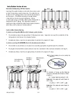
Back to back Configuration (2 to 8 water heaters)
In Line Configuration (2 to 8 water heaters)
Refer to the Ubbink appendix of this manual for the vent system assembly instructions.
Follow these Rinnai installation instructions in this manual in addition to the Ubbink vent system assembly
instructions.
Install the venting according to one of the 2 configurations below. Do not locate the common vent remotely
from the water heaters. (Room air configurations follow the same instructions excluding information regarding
air intake.)
The installation area should be measured to make sure that adequate space is available to install the water
heaters and venting system.
NOTE: Dimensions above
are used in all back to back
configurations
Note: If water heaters are mounted directly on a wall, air intake piping will need to be in front of the appliance
adapters. The intake header in the drawing above has been removed for illustration purposes.
7”
(178mm)
6.25”
(159mm)
TYPICAL
20.5” (520)
3°
1”
(2
5mm
)
2”
(5
1mm
)
3”
(7
6mm
)
EXHAUST
AIR
INTAKE
1”
(2
5mm
)
2”
(5
1mm
)
3”
(7
6mm
)
3°
4”
(1
01
mm
)
5”
(1
27
mm
)
6”
(1
52
mm
)
7”
(1
78
mm
)
TYPICAL
20.5” (520)
AIR
INTAKE
EXHAUST
Summary of Contents for c199i
Page 43: ...43 Rinnai CVent NOTES ...
Page 86: ...86 CVent de Rinnai NOTES ...
Page 87: ...87 CVent de Rinnai NOTES ...


