background image

11

Rinnai  Corporation

V3237  Models

Diagnostic  Use  of  Controller

1. 

To  Display  Maintenance  Codes:    Press  the  ‘On/Off’  button  once  to  turn  the  controller  off.  
Press  and  hold  the  ‘On/Off’  button  followed  by 

  thermostat  button  to  cycle  through  the 

maintenance  codes.     

2. 

To  Display  Water  Flow  through  the  water  heater:    Press  the 

  thermostat  button  and 

hold  for  2  seconds  and  then  press  the  ‘On/Off’  button  while  continuing  to  hold  the 
thermostat  button.

3. 

To  Display  Outlet  Water Temperature:    Press  the 

  thermostat  button  and  hold  for  2 

seconds  and  then  press  the  ‘On/Off’  button  while  continuing  to  hold  the 

  thermostat 

button.       

To  Change  the  Temperature  Display  from  °F  to  °C  (or  °C  to  °F)

1. 

Press  the  ‘On/Off’  button  once  to  turn  the  controller  unit  off.    With  the  controller  off 
press  and  hold  the  ‘On/Off’  button  until  the  display  changes  to  °C  (°F),  approximately  5 
seconds.

To  Turn  Off  the  Sound  (Mute)

1. 

To  turn  the  sound  off  (mute)  press  and  hold  both  the 

  and 

  thermostat  buttons  until 

an  audible  “beep”  is  heard,  approximately  5  seconds.


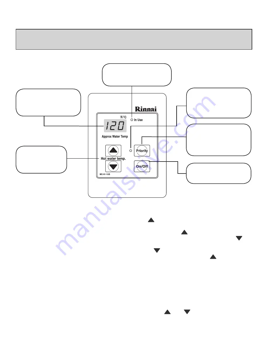
Digital  Display

I

ndicates  the  selected  water

temperature.  Error  messages
flash  in  the  event  of  a  failure.


Thermostat

Increases  or  decreases 
the  desired  water 
temperature.


In  Use  Indicator

Indicates  that  the  hot  water 
heater  is  in  operation.


ON/OFF  Button

        Used  to  switch  the 
      water  heater  on  and  off.


Priority  Button

Pressing  takes  control  of  the     
water  temperature  by  this 
controller  only  when  all  taps 
are  off.


Priority  Indicator

      Indicates  whether  this
      controller  has  priority
      control  over  the  water                  
      temperature 

REMOTE CONTROLLER OPERATION

U273-430(00).indd   11

06.2.8   10:36:44 AM

Summary of Contents for C98e

Page 1: ...is or any other appliance WHAT TO DO IF YOU SMELL GAS Do not try to light any appliance Do not touch any electrical switch do not use any phone in your building Immediately call your gas supplier from a neighbor s phone Follow the gas supplier s instructions If you cannot reach your gas supplier call the fire department Installation and service must be performed by a qualified installer service ag...

Page 2: ...eatures of Your New Water Heater Safety Considerations Basic Operation General Controller Information Remote Controller Operation Deluxe Controllers Controllers Set Pattern Temperature Tables Error Messages Maintenance Service Information Trouble Shooting and Common Questions For Your Safety Read Before Operating Operating Instructions Care Lime Condition Warning Installer s Instructions Notes ...

Page 3: ... 8 GPM 98 F 55 Lbs 49 dB A 2 watts 116 watts Electronic 6 W C 10 W C 10 5 W C 13 5 W C Temperature controlled continuous flow gas hot water system With or without remote controls mounted in kitchen bathroom etc Direct Vent Forced Combustion Natural Gas or Propane Ensure unit matches gas type it s being installed on Gas Supply 3 4 MNPT Cold Water Inlet 3 4 MNPT Hot Water Outlet 3 4 MNPT Direct Elec...

Page 4: ...stem and all circulating water flows through the water heater WHAT WILL RINNAI DO Rinnai will repair or replace the product or any part or component that is defective in materials or workmanship except as set forth below Rinnai will pay reasonable labor and shipping costs to repair the product All repairs must be performed using genuine Rinnai parts All repairs or replacements must be performed by ...

Page 5: ...ranty WHAT IS NOT COVERED This Warranty does not cover any failures or operating difficulties due to accident abuse misuse alteration misapplication acts of God improper installation improper maintenance or service inadequate water quality scale buildup freeze damage or for any other causes other than defects in materials or workmanship This warranty does not apply to any product whose serial numbe...

Page 6: ...ational Fuel Gas Code ANSI Z223 1 NFPA 54 and or the CSA B149 1 Natural Gas and Propane Installation Code FOR INDOOR UNITS These models have the FFU designation ONLY Install this product indoors DO NOT install outdoors FOR OUTDOOR UNITS These models have the W designation ONLY Install this product outdoors DO NOT install indoors Do Not use this appliance if any part has been underwater Immediately...

Page 7: ... ignite once the outgoing hot water temperature falls below the selected temperature F Built into the microprocessor of the Rinnai is the ability to LIMIT THE MAXIMUM TEMPERATURE of the hot water supplied by the Rinnai Water Heaters Without the connection of a remote controller s the Rinnai Water Heater is preset to deliver water at 120O F Residential and 140O F Commercial F Residential Unit With ...

Page 8: ...Controller s and the temperature of the water at the tap The Rinnai Water Heater controls the water temperature automatically To do this it sometimes needs to change the water flow accordingly The water flow from the hot water tap may vary after the selected temperature at the remote controller s is altered The water flow may also vary from summer to winter as incoming water temperatures differ The v...

Page 9: ...t be closed and all circulating pumps turned off where applicable The temperature displayed on this remote controller will also be displayed on all other Remote Controller s 3 Simply press the or button until the desired temperature is displayed on the Digital Monitor 4 2 indicates that the Rinnai Water Heater is ready to supply hot water at the set temperature as soon as a tap is opened Note The ...

Page 10: ...ATION The controller s for the Rinnai water heaters allow the customer to control the functions of the water heater and to diagnose certain fault conditions REMOTE CONTROLLERS IDENTIFICATION MC 91 1US comes with the unit MC 100V 1US optional BC 100V 1US optional ...

Page 11: ...ress the On Off button once to turn the controller unit off With the controller off press and hold the On Off button until the display changes to C F approximately 5 seconds To Turn Off the Sound Mute 1 To turn the sound off mute press and hold both the and thermostat buttons until an audible beep is heard approximately 5 seconds Digital Display Indicates the selected water temperature Error messa...

Page 12: ... PM clock In the event of a fault codes for error messages will flash here Call Allows user to contact another controller Can be used as a communication channel for errands or in emergency situations In Use Indicator Indicates that the hot water heater is in operation Priority Pressing takes control of the water temperature by this controller only when all taps are off Call Allows user to contact ...

Page 13: ... get close to the time you wish to set press the button intermittently to avoid going further than the desired time Press the Function Button again to complete setting the clock and return to normal operation Adjusting Temperature Simply press the and buttons until the desired temperature is displayed on the Digital Display To operate the hot water unit open any hot water tap This will automatical...

Page 14: ...ttons until the desired temperature is displayed on the Digital Display To Operate the product open any hot water tap This will automatically light the burner providing hot water The In Use Indicator will illuminate on the Temperature Controller Once the hot water is running if the set temperature is either too hot or cold press the Hot water temp or buttons until the desired temperature is reache...

Page 15: ...temperature use the Temp or buttons The selected temperature will be displayed on the bathroom controller monitor and will remain as the default temperature until it is changed To select the volume of water to be used by the shower bath use the Water Vol or buttons The selected water volume is numerically displayed at the right of the controller monitor When filling a bath for the first time it is r...

Page 16: ... Water Smart Bath Fill Operations Finishes Once the Water Smart Bath Fill operation finishes the following events will occur 1 The flow from the shower bath hot water tap will cease 2 The Water Smart Bath Fill button will flash 3 The Kitchen Controller Bath indicator will flash Deluxe Models 4 A tone will sound 5 The voice prompt will say Bath fill is complete Turn off the bath hot water tap and push t...

Page 17: ...atures more comfort able Maintaining lower temperatures helps save energy To obtain water temperatures lower than 98O F simply add cold water Deluxe Controllers are an optional extra Controllers and Deluxe Controllers can be installed together Controllers allow temperature selection only Deluxe Controllers have temperature selection bath fill and clock functions Controllers allow the water temperat...

Page 18: ...correct Ensure gas line meter and or regulator is sized properly Bleed all air from gas lines Verify dip switches are set properly Ensure appliance is properly grounded Disconnect all MSA controls Ensure igniter is operational Check igniter wiring harness for damage Check gas solenoid valves for open or short circuits Remove burner cover and ensure all burners are properly seated Remove burner pla...

Page 19: ...sor of scale build up Replace sensor Check for restrictions in air flow around unit and vent terminal Check sensor wiring for damage Measure resistance of sensor Clean sensor of scale build up Ensure fan blade is tight on motor shaft and is in good condition Replace sensor Check modulating gas solenoid valve wiring harness for loose or damage terminals Measure resistance of valve coil Ensure fan w...

Page 20: ...power Allow to cool for one hour 2 Remove the Front Panel by removing screws See parts breakdown on panels 3 Use pressurized air to remove dust from around main burner 4 Use soft dry cloth to wipe cabinet DO NOT DAMAGE OR DISTORT ANY PARTS OF HEATER DO NOT USE WET CLOTH OR SPRAY CLEANERS ON BURNER 2 Visual check of main burner flames The burner must flame evenly over the entire surface when operatin...

Page 21: ...ssure relief valve must be manually operated once a year to check for correct operation In the case of any error code refer to the error message section of this manual or call your Rinnai Authorized Service provider or Rinnai at 800 621 9419 Should overheating occur or the gas supply fail to shutoff turn off the manual gas control valve to the appliance DO NOT ATTEMPT TO SERVICE YOUR Rinnai Water ...

Page 22: ...22 Rinnai Corporation V3237 Models M A I N T E N A N C E S E R V I C E I N F O R M A T I O N FLUSH PROCEDURE FOR LC ERROR CODE ...

Page 23: ... if not already incorporated as part of the water heater as shown The drip leg must be at least three inches long for the accumulation of dirt foreign material and water droplets M A I N T E N A N C E S E R V I C E I N F O R M A T I O N Freeze Protection ...

Page 24: ...by the Rinnai Water Heater at the remote control or increase your total flow Q White smoke comes out of the exhaust A During colder weather when the exhaust temperature is hotter than the air the exhaust fumes condense producing white steam this is normal Q When I open a hot water tap I do not immediately get hot water A Hot water must travel through your plumbing from the Rinnai Water Heater to th...

Page 25: ...ced or attempted repair may result in a fire or explosion D Do not use this appliance if any part has been under water Immediately call a qualified service technician to inspect the appliance and to replace any part of the control system and any gas control which has been under water 6 Wait 5 minutes to clear out any gas If you then smell gas STOP Follow B in the safety information above If you don ...

Page 26: ...se fading of the paint Lime Condition Warning Signal If you notice LC flashing on the remote key pad this means the unit is beginning to lime up and MUST be flushed Contact a Qualified Service Technician to flush the appliance Failure to flush the appliance when LC is flashing will cause damage to the heat exchanger Damage caused by lime build up is not covered by the unit s warranty To reset the LC Fau...

Page 27: ...f Installer s Manual www rinnai us 800 621 9419 Installer s Installation Considerations 28 29 30 Water Piping Notes 30 Venting 31 32 33 34 Performance Data 35 Product Dimensions 36 37 Easy Connect EZConnect instructions 38 Pressure Relief Valve 39 Gas Pressure Check List 39 Gas Piping Notes 40 Gas Piping Sizing Charts 41 Recommended Piping Installations 42 43 44 Electrical Connection Notes 45 Remo...

Page 28: ...ll a Pressure Relief Valve Pipe pressure relief discharge to a drain or outside environment see pressure relief valve page for details of requirements 7 The appliance should be located in an area where water leakage from the unit or connections will not result in damage to the area adjacent to the appliance or to lower floors of the structure When such locations cannot be avoided it is recommended...

Page 29: ...ential 3 The Rinnai is not suitable for use as pool or spa heater 4 The indoor unit is designed to be installed indoors using the proper vent piping to exhaust by products of combustion to the outside environment Contact your dealer or Rinnai for proper vent kits DO NOT operate this unit without vent piping connected Exhaust gasses must be expelled outside the home All pipe joints shall be taped t...

Page 30: ...vironment see pressure relief valve page for details of requirements 1 A manual water control valve must be placed in the water inlet connection to the Rinnai before it is connected to the water line Unions may be used and are recommended on both the hot cold water supply lines for the future servicing or disconnection of the unit 2 All soldering materials and piping must be compatible with potabl...

Page 31: ...ure 1 Short horizontal vent runs without a condensate drain must slope to the vent termination 1 4 per foot Vertical terminations or long horizontal terminations must incorporate a condensate drain and trap as close as possible to the appliance The condensate drain trap must contain a minimum of 3 of water Dispose of condensate per local codes Horizontal Venting Vertical Venting FIGURE 1 Note Some...

Page 32: ...pipe of any other water heater or appliance Vent connections must be firmly pressed together so that the gaskets form an air tight seal Refer to the vent pipe manufacturers instructions for component assembly instructions Air Intake Connection Refer to Figure 2 1 Predrill two small holes at the end of the air intake pipe 2 Slide the pipe over the air intake terminal 3 Using a level ensure the pipe...

Page 33: ...Figure 6 for air inlet and exhaust outlet termination minimum clearances Figure 4 Listed and Tested Vent Products EXHAUST INTAKE RELATIONSHIP Manufacturer Product Appliance Adapter Vertical Termination Horizontal Termination Horizontal Concentric Termination Heat Fab Saf T Vent 9401AMTK 5400CI 9492 NA Z Flex Z Vent 2SVSNA04 5 2SVSRCF4 2SVSTPX4 NA ProTech Systems FasNSeal FSAAU4 FSRC4 FSBS4 Metal F...

Page 34: ...ertical clearance to ventilated soffit eaves or overhang E Clearance to unventilated soffit eaves or overhang F Clearance to outside corner G Clearance to inside corner H Clearance to each side of center line extended above meter regulator assembly 3 feet within a height 15 feet above the meter regulator assembly I Clearance to service regulator vent outlet 3 feet J Clearance to nonmechanical air ...

Page 35: ...35 Rinnai Corporation V3237 Models PRESSURE DROP CURVE OUTLET FLOW DATA 0 0 0 2 0 4 0 6 0 8 0 0 1 0 2 1 0 5 1 5 2 1 0 0 1 5 7 0 5 5 2 0 F e s i R e r u t a r e p m e T T Hot Water Flow Rate gpm ...

Page 36: ...36 Rinnai Corporation V3237 Models PRODUCT DIMENSIONS INDOOR UNIT ...

Page 37: ...37 Rinnai Corporation V3237 Models PRODUCT DIMENSIONS OUTDOOR UNIT FITTING DIAMETER A C F J H E I G D B ...

Page 38: ...Installation Layout 5 Before installing the EZConnect cord remove the protective cap from the 3 pin connector marked EZConnect located in the wiring harness of the Primary Unit Fig 1 6 To install the EZConnect cord plug in the cord on both the Sub unit and Primary unit accordingly see installation layout above Fig 2 3 7 Securely tighten the EZConnect cord to the bottom of Water Heater by using Cab...

Page 39: ...tall any reducing fittings or other restrictions in the relief line The relief line should allow for complete drainage of the valve and the line 5 If a relief valve discharges periodically this may be due to thermal expansion in a closed water supply system Contact the water supplier or local plumbing inspector on how to correct this situation Do not plug the relief valve 6 Should overheating occur...

Page 40: ...ble solution as applicable 5 The Rinnai Water Heater and its individual shut off valve must be disconnected from the gas supply piping system when pressure testing of the gas supply piping system at test pressures greater than 1 2 psi 3 5 kPa 6 Always use approved connectors to connect the unit to the gas line Always purge the gas line of any debris before connection to the water heater 7 The Rinn...

Page 41: ...ic feet hour table assumes 0 3 inch pressure drop specific gravity of 0 60 Nominal Length of Pipe in Feet Iron Pipe Size Inches 10 20 30 40 50 60 70 80 90 100 125 150 175 200 3 4 278 190 152 130 115 105 96 90 84 79 72 64 59 55 1 520 350 285 245 215 195 180 170 160 150 130 120 110 100 1 1 4 1050 730 590 500 440 400 370 350 320 305 275 250 225 210 1 1 2 1600 1100 890 760 670 610 560 530 490 460 410 3...

Page 42: ...42 Rinnai Corporation V3237 Models RECOMMENDED PIPING FOR BASIC INSTALLATION ...

Page 43: ...lve KEY Minimum 3 4 Cold Water Supply Line 2 5 Gallon Electric Water Heater 120 F Building Fixtures Building Return Not required to be 3 4 Line Building Supply Expansion Tank Gas Supply QTY 1 1 1 Rinnai Water Heater Pump Should be Controlled by an Aquastat Timer or Combination Aquastat and Timer Pump to be sized for Pressure Drop through Building Supply and Return Piping Pump to be of Bronze or St...

Page 44: ...44 Rinnai Corporation V3237 Models OPTIONAL PIPING FOR CIRCULATION SYSTEMS ...

Page 45: ...le for outdoor use Check National Electrical Codes for proper type switch to use in your area The Rinnai Water Heater must be electrically grounded in accordance with local codes or in the absence of local codes with the most recent edition of the National Electrical Code ANSI NFPA 70 In Canada all electrical wiring to the Rinnai Water Heater should be in accordance with local codes and the Canadi...

Page 46: ...r 3 Avoid direct sunlight The digital display can be difficult to read in direct sunlight 4 Avoid areas where the remote controller can be splashed with water oil sauce etc 5 The remote controller cables carry low voltage 12VDC digital When the Temperature Controller is used in public applications it should be installed where it can not be adjusted by the public i e a maintenance room or manager s ...

Page 47: ...e plastic cover from the PCB and electrical connections 10 Thread the cable through the access hole at the base of the unit and connect the wires to the controller terminals on the right hand side bottom of the PCB 11 Secure the controller cable using the clamp provided 12 Replace plastic cover over PCB and then replace the cover of the Rinnai Water Heater DO NOT ATTEMPT TO CONNECT THE REMOTE CONT...

Page 48: ... Temperatures over 125 F can cause severe burns instantly or death from scalds Hot Water can cause first degree burns with exposure for as little as 3 seconds at 140 F 20 seconds at 130 F 8 minutes at 120 F Test the temperature of the water with your elbow before placing a child in the bath or shower Do not leave a child or an infirm person in the bath or shower unsupervised BURN A B O U T H O T W A...

Page 49: ...49 Rinnai Corporation V3237 Models INSTALLER S INSTALLATION INSTRUCTIONS Schematic Diagram V3237FFU R98 V3237FFUC C98 V3237W R98 V3237WC C98 ...

Page 50: ...ING Temperature control Gas pressure Gas type Y BR O R W G 4 W W W P W W OUTGOING WATER THERMISTOR HEAT EXCHANGER WATER THERMISTOR Y R BR W 4 1 H O BY PASS FLOW CONTROL DEVICE WATER FLOW CONTROL DEVICE COMBUSTION FAN THERMAL FUSES OVERHEAT SWITCH QS WATER FLOW SENSOR FLAME ROD MODULATING SOLENOID VALVE H 1 COLOR CODING W White BK Black BR Brown R Red BL Blue Y Yellow P Pink O Orange G Green GY Gra...

Page 51: ...rporation V3237 Models N O T E S Model Number _____________________________________________ Serial Number _____________________________________________ Date of Purchase _____________________________________________ ...

Page 52: ...060 00012 30082 6 U273 430 ...

Reviews: