12
Rinnai Direct Vent Service Manual
RHFE-201FA
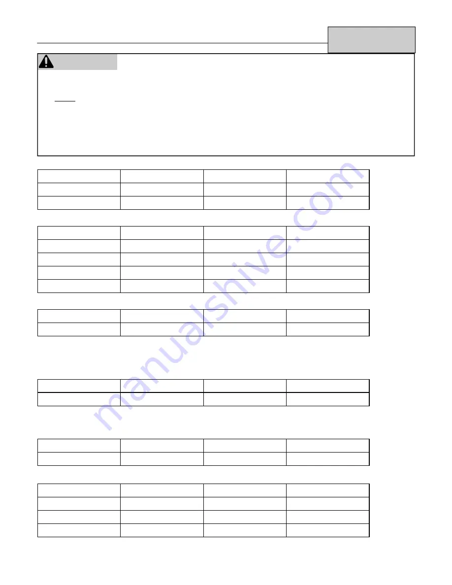
Troubleshooting
(AC
IN)
(Connector
B)
Black-White
120 VAC
CONNECTOR B
Pin # 1-2
Black-Ground
120 VAC
Pin #2-Ground
White-Ground
0 VAC
Pin #1-Ground
(TR) Transformer:
(Connector C) (AC Out)
Read voltage across:
Voltage Potential
Read resistance
Pin Numbers
Grey-Grey 90-110
VAC
3-6
Ω
Pin
#1-7
Red-Yellow 30-42
VAC
0.8-1.5
Ω
Pin
#4-5
Blank pin-Grey
15-21 VAC
0.6-1.2
Ω
Pin
#6-7
Grey-Black 180-220VAC
155-260
Ω
Pin
#7-8
(SP) Sparker:
(Connector D) (Voltage potential while Sparking)
Read voltage across:
Voltage Potential
Read resistance
Pin Numbers
Red-Blue 85-100
VAC
100K-120K
Ω
Pin
#3-6
The spark must be sensed as being at the correct location and intensity before it will allow the gas valve to open. Check
across Pin # 1-2 at Connector F and you should read 4-6 VDC potential. When sparking, if the spark is in the right location and
intensity the voltage potential will drop to almost 0 (zero) and then return to the 4-6 VDC potential.
(SV1 and SV2) Main Solenoid Valves: (Connector D)
Read voltage across:
Voltage Potential
Read resistance
Pin Numbers
Black-Yellow 85-90
VDC
700-1000
Ω
Pin
#1-4
*Resistance across each coils terminals should be 1400-2000
Ω
when isolated.
(POV) Modulating Gas Valve (Connector G)
Read voltage across:
Voltage Potential
Read resistance
Pin Numbers
Grey-Grey 6-16
VDC
80-90
Ω
Pin
#2-6
(BL) Combustion Blower Motor:
(Connector G) DC Motor 37VDC 8 Watts
Read voltage across:
Voltage Potential
Read resistance
Pin Numbers
Black-White 7-12
VDC
8K-10K
Ω
Pin
#7-8
Yellow-White 4-5
VDC
4K-6K
Ω
Pin
#4-8
Red-White
10-30 VDC
N/A
Pin # 3-8
WARNING
There are a number of live tests that are required when fault finding this product. Extreme care should be used at
all times to avoid contact with energized components inside the furnace.
You MUST be a qualified service person before proceeding with these test instructions.
Before checking resistance readings, turn off power source to unit and then isolate each item to be checked from
the circuit by unplugging it.
When setting gas pressures on one of these units, please check the complete model number you are trouble-
shooting. Gas pressures and dip switches can vary among models. Always check the rating plate for complete
information and follow directions.
Summary of Contents for Energysaver RHFE-1004FTA
Page 14: ...14 Rinnai Direct Vent Service Manual RHFE 201FA RHFE 201RFA Wire Diagram ...
Page 15: ...Rinnai Direct Vent Service Manual 15 RHFE 201FA RHFE 201RFA Ladder Diagram ...
Page 18: ...18 Rinnai Direct Vent Service Manual RHFE 263FA RHFE 263FAII RHFE 263RFA Wire Diagram ...
Page 19: ...Rinnai Direct Vent Service Manual 19 Ladder Diagram RHFE 263FA RHFE 263FAII RHFE 263RFA ...
Page 26: ...26 Rinnai Direct Vent Service Manual RHFE 431FA Series RHFE 556FA FTRA Wire Diagram ...
Page 27: ...Rinnai Direct Vent Service Manual 27 RHFE 556FAIII Wire Diagram ...
Page 28: ...28 Rinnai Direct Vent Service Manual RHFE 556FTRAIII Wire Diagram ...
Page 32: ...32 Rinnai Direct Vent Service Manual RHFE 431WTA Wire Diagram ...
Page 33: ...Rinnai Direct Vent Service Manual 33 RHFE 556WTA Wire Diagram ...
Page 45: ...Rinnai Direct Vent Service Manual 45 RHFE 551FA Fault Finding Summary ...
Page 46: ...46 Rinnai Direct Vent Service Manual RHFE 551FA Fault Finding Chart 1 ...
Page 47: ...Rinnai Direct Vent Service Manual 47 RHFE 551FA Fault Finding Chart 2 ...
Page 48: ...48 Rinnai Direct Vent Service Manual RHFE 551FA Fault Finding Chart 3 ...
Page 49: ...Rinnai Direct Vent Service Manual 49 RHFE 551FA Fault Finding Chart 4 ...
Page 50: ...50 Rinnai Direct Vent Service Manual RHFE 551FA Fault Finding Chart 5 ...
Page 51: ...Rinnai Direct Vent Service Manual 51 RHFE 551FA Fault Finding Chart 6 ...
Page 52: ...52 Rinnai Direct Vent Service Manual RHFE 551FA Fault Finding Chart 7 ...
Page 53: ...Rinnai Direct Vent Service Manual 53 RHFE 551FA Fault Finding Chart 8 ...
Page 54: ...54 Rinnai Direct Vent Service Manual RHFE 551FA Fault Finding Chart 9 and 10 ...
Page 55: ...Rinnai Direct Vent Service Manual 55 RHFE 551FA Wire Diagram ...
Page 58: ...58 Rinnai Direct Vent Service Manual RHFE 1001FA Fault Finding Chart ...
Page 59: ...Rinnai Direct Vent Service Manual 59 RHFE 1001FA Fault Finding Chart ...
Page 60: ...60 Rinnai Direct Vent Service Manual RHFE 1001FA Fault Finding Chart ...
Page 61: ...Rinnai Direct Vent Service Manual 61 RHFE 1001FA Wire Diagram ...
Page 64: ...64 Rinnai Direct Vent Service Manual RHFE1001FA VA Fault Finding Chart ...
Page 65: ...Rinnai Direct Vent Service Manual 65 RHFE1001FA VA Fault Finding Chart ...
Page 66: ...66 Rinnai Direct Vent Service Manual RHFE1001FA VA Fault Finding Chart ...
Page 67: ...Rinnai Direct Vent Service Manual 67 RHFE1001FA VA Fault Finding Chart ...
Page 68: ...68 Rinnai Direct Vent Service Manual RHFE 1001FA VA Wire Diagram Wire Diagram Ladder Diagram ...
Page 73: ...Rinnai Direct Vent Service Manual 73 RHFE 1004FA RHFE 1004RFA RHFE 1004FTA Wire Diagram ...


