background image

3

OPERATION

After the heater is properly assembled and all
gas connections to the regulator have been
tested for gas tightness (

Refer page 9, To test

for gas tightness.

), the heater is ready for

operation.

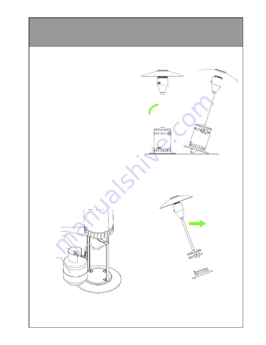
Connecting gas bottle:

1 Slide the bottle cover up until it is clear of

the leg assembly and rests on  top of legs
so that it will not fall down while you are
installing the bottle.

2 ALWAYS CHECK THE GAS SUPPLY

HOSE FOR DAMAGE BEFORE
PROCEEDING AND  HAVE THE HOSE
REPLACED  IF THERE ARE ANY
CRACKS, HOLES, ABRASION MARKS
OR SIGNS OF PERISHING.

3 Attach the regulator to the bottle NOTE: the

thread on the regulator tightens by turning
counter-clockwise.

4 Fully open the valve on the gas bottle and

check the connection for leaks as described
in the assembly instructions.

5 Replace the bottle cover so that it is resting

completely on the base, taking care not to
trap the gas supply hose against the legs.

Bottle cover

Leg flange

Gas bottle

Valve

Regulator

Moving the heater

1 With the controls facing towards you, tip the

heater backwards.

2 Fold the wheels outwards as shown and

lower the lifted edge onto the wheels.

3 Tip the heater back in the opposite direction

until the heater is balanced and move to
desired location.

4 To retract the wheels simply push the heater

backwards again until the wheels are
hanging straight down and stand the heater
back up (the wheels should fold away without
any further assistance).

5 NOTE: The heater will not light unless the

wheels are retracted

IMPORTANT: YOU MUST TEST THIS
CONNECTION FOR GAS TIGHTNESS
BEFORE OPERATING THE HEATER.

Refer page 9, To test for gas tightness.

Summary of Contents for PATIOSSL

Page 1: ...on CodeAG601 NZ 5261 Any other relevant statutory regulation For Outdoor Use Only LP Gas Only FEATURES Completely self contained High efficiency radiant plaques Stainless steel construction Battery ig...

Page 2: ...damage the gas hose when assembling the appliance and when fitting or removing the gas bottle and bottle cover In the event of damage being evident cracks tears abrasionetc thehosemust be replaced imm...

Page 3: ...the connection for leaks as described in the assembly instructions 5 Replace the bottle cover so that it is resting completely on the base taking care not to trap the gas supply hose against the legs...

Page 4: ...t the battery is properly installed and has a charge 6 When the main burner has ignited then hold the knob down for a further 15 seconds to maintain ignition 7 Once ignition has been established the s...

Page 5: ...REA Definition of an outdoor area The following diagrams show the definition of an outdoor area as described inAG405 This appliance must not be operated in a confined space that does not meet these re...

Page 6: ...6 OUTDOOR AREA CONTINUED...

Page 7: ...d leg flange have been bolted together for shipping purposes and will need to be separated before assembly can begin There is also a rubber edging strip around the lower rim of the burner tube This wi...

Page 8: ...crews as this may strip the threads 5 Slide the stainless steel bottle cover assembly over the pole then remove the protective rubber strip from the end of the burner assembly spigot tube Remove the b...

Page 9: ...embly under battery cover Gas supply hose Regulator Paint brush with soap solution 12 Attach the gas supply hose refer page 3 connecting gas bottle to the regulator and tighten using a spanner IMPORTA...

Page 10: ...rol Rinnai lever control combination Burner Radiant plaque Regulator POL 2 74 Kpa Test point pressure 2 55 kPa Gas type LPG Ignition Battery spark Battery 1 5 V c size Outer materials 304 Stainless st...

Reviews: