


4
OPERATION CONTINUED
Lighting the heater
Once the heater is properly assembled and has
been checked for leaks
,
it is ready for
operation
.( Refer page 9, To test for gas
tightness.)
1 Place the heater outdoors and ensure that the
minimum clearances to combustible materials
are met. (
See pages 5 and 6, for definition of
outdoor area)
2 Make sure the heater is sitting on a firm flat
surface with the wheels retracted and all the
guards are in place, with the bottle cover sitting
on the base. NOTE: The heater will not start if
it is not standing straight up.
3 Check that both control knobs are in the off
(0) position.
4 Fully open the valve on the gas bottle.
5 Press and hold the ignition (right hand ) knob
down to the ignition symbol. You should hear
a ticking noise from the spark ignition. If there
is no sound then check that the battery is
properly installed and has a charge.
6 When the main burner has ignited then hold
the knob down for a further 15 seconds to
maintain ignition.
7 Once ignition has been established the
second control knob can be used to control
the top burner
8 If the burner fails to ignite or stay alight then
wait at least 5 minutes before trying again.
Shutting down the heater
1 To turn the heater off, close the valve on the
gas bottle.
2 Once the flame has extinguished, set both
control knobs to the off position.
Top
Burner
off
on
Main
Burner
off
on
ignition
(2155)
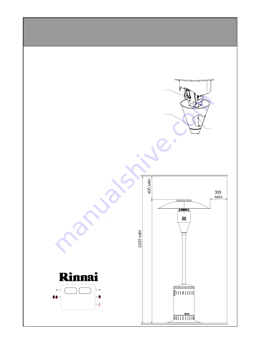
Changing the battery
Press the release button on the back of the pole
and slide the battery cover down to allow access
to the battery. Replace using a C size battery
only.
Minimum clearances
This appliance must not be operated unless the
following distances are maintained between the
heater and any combustible material
Ensure that any curtains or shade cloths etc. are
secured and will not get near the heater.
Release
button
Battery
cover
Battery
Summary of Contents for PATIOSSL
Page 6: ...6 OUTDOOR AREA CONTINUED...


