background image

9

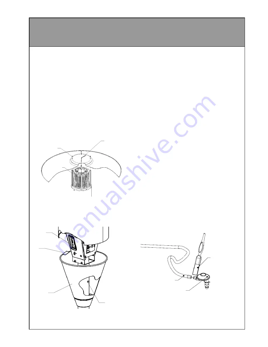
9 Remove the plastic wrap from the burner

assembly and carefully place the hood on
top of the burner assembly as shown
below, and align the four holes in the hood
with the chrome rods on the burner
assembly.

10 Using the 4 mm allen key (this is held by a

plastic clip on the side of the burner
assembly) attach the hood using the
stainless steel button head cap screws. Do
not tighten the screws until all four are in
place. You may need to tilt the unit over or
use a step ladder to attach the hood.

11 Remove the plastic tag from the end of the

battery terminal and slide the battery cover
up until it passes the button on the pole.

M6 x 12

Button-head

cap screw

Chrome bar

4 mm Allen key
stored on side
of burner assembly
under battery cover

Gas supply hose

Regulator

Paint brush
with soap solution

12 Attach the gas supply hose 

(refer page 3,

connecting gas bottle)

 to the regulator  and

tighten using a spanner.

IMPORTANT: YOU MUST TEST THIS
CONNECTION FOR GAS TIGHTNESS
BEFORE OPERATING THE HEATER.

Release
button

Battery

Transit
tag

Battery
cover

To test for gas tightness:
1 Fit the regulator to a properly filled gas bottle

and tighten by hand. (Note: turn fitting counter-
clockwise to tighten)

2 Fully open the valve on the gas bottle.
3 Using a brush or spray bottle, apply a  solution

made up of liquid soap and water to all gas
connections to the regulator.

4 If bubbles appear  then there is a leak .
5 If a leak is detected you must shut off the valve

immediately. Re-tighten the leaking connection
and re-test. If a leak is still detected then
contact the retailer where the appliance was
purchased from or an approved service
technician.

Summary of Contents for PATIOSSL

Page 1: ...on CodeAG601 NZ 5261 Any other relevant statutory regulation For Outdoor Use Only LP Gas Only FEATURES Completely self contained High efficiency radiant plaques Stainless steel construction Battery ig...

Page 2: ...damage the gas hose when assembling the appliance and when fitting or removing the gas bottle and bottle cover In the event of damage being evident cracks tears abrasionetc thehosemust be replaced imm...

Page 3: ...the connection for leaks as described in the assembly instructions 5 Replace the bottle cover so that it is resting completely on the base taking care not to trap the gas supply hose against the legs...

Page 4: ...t the battery is properly installed and has a charge 6 When the main burner has ignited then hold the knob down for a further 15 seconds to maintain ignition 7 Once ignition has been established the s...

Page 5: ...REA Definition of an outdoor area The following diagrams show the definition of an outdoor area as described inAG405 This appliance must not be operated in a confined space that does not meet these re...

Page 6: ...6 OUTDOOR AREA CONTINUED...

Page 7: ...d leg flange have been bolted together for shipping purposes and will need to be separated before assembly can begin There is also a rubber edging strip around the lower rim of the burner tube This wi...

Page 8: ...crews as this may strip the threads 5 Slide the stainless steel bottle cover assembly over the pole then remove the protective rubber strip from the end of the burner assembly spigot tube Remove the b...

Page 9: ...embly under battery cover Gas supply hose Regulator Paint brush with soap solution 12 Attach the gas supply hose refer page 3 connecting gas bottle to the regulator and tighten using a spanner IMPORTA...

Page 10: ...rol Rinnai lever control combination Burner Radiant plaque Regulator POL 2 74 Kpa Test point pressure 2 55 kPa Gas type LPG Ignition Battery spark Battery 1 5 V c size Outer materials 304 Stainless st...

Reviews: