Energysaver remote switching kit installation
10828-A ┃ 01:16
Energysaver remote switching kit installation guide (R1349)
Rinnai New Zealand Ltd.
(0800 746 624)
2 of 2
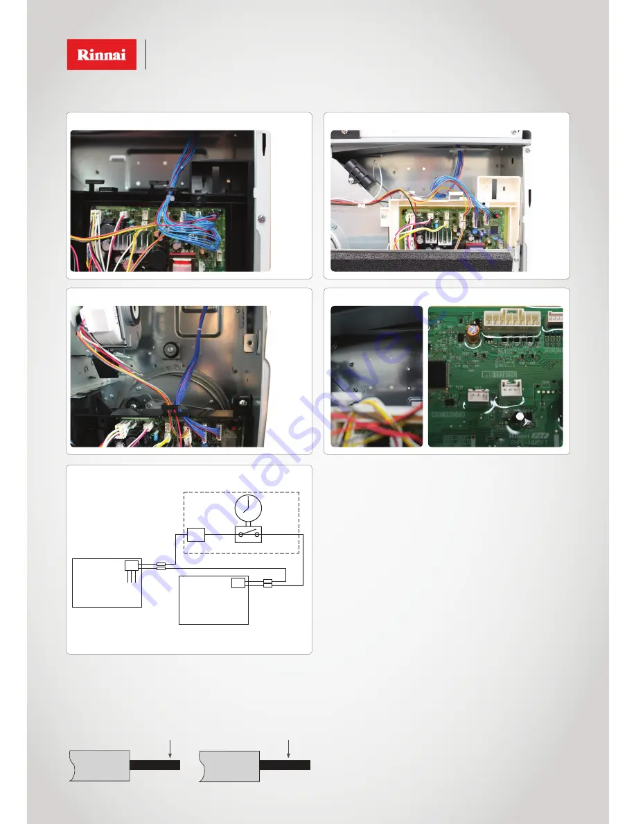
Suggested remote switching Energysaver layout
When a 24 Volt AC supply is applied to the sub-PCBs the appliances will turn on. When the 24 Volt AC power
supply is disconnected appliances will turn off.
Timer or
manual switch
Switch circuit
power supply
24 V
AC
Must be AC
Terminal
block
Rinnai Energysaver
Rinnai Energysaver
black
black
Sub
PCB
white
re
d
blue
Installer to supply
Energysaver 309FT
Energysaver 561FT
1
2
1
2
Energysaver 559FT
Energysaver 1005FT
1
= rear panel position to secure sub-PCB (for the 1005FT you need to temporarily relocate the main-PCB to access the rear panel)
2
= port connection (309FT - CN7, 561FT - CN7, 559FT - CN7, 1005FT - CN18)
1
2
Recommended electrical cable specification
Multi-core conductor: 1.25 mm
2
, AWG 16 single cable: Ø 1.2 mm, AWG 16.
Recommended cable
Multi-core conductor: 1.25 mm
2
, AWG 16~0.3 mm
2
, AWG 22 single cable:
Ø 1.6 mm, AWG 14~Ø0.5mm, AWG 20.
Strip length
8-9 mm.
Cable connection warning
• When a multi-core conductor is used as the connection cable, solder the end of the cable so that the core is prevented from spreading and
the cable grip holds securely.
• Only connect one cable per connection opening.
• Lock the cable clamp lever securely after fitting the cable.
Soldering
Total soldering
OR
1
2


