40
Rinnai Tankless Water Heater Installation and Operation Manual
Figure 35
Figure 36
Table 19
4.11 Recirculation
Including recirculation can reduce the amount of
time it takes hot water to get to your fixture. This
model water heater includes the ability to control
a recirculation pump. Two modes are available,
Economy and Comfort.
•
Economy Mode—Cycles the pump less
often, using less energy to maintain the
circulation loop temperature.
•
Comfort Mode—Cycles the pump more
frequently, ensuring the loop
temperature remains higher (but also uses
more energy).
Recirculation mode is for residential installations
only. Recirculation mode cannot be used with an
air handler or with multiple Rinnai water heaters.
The maximum Rinnai temperature setting while in
recirculation mode is 140°F (60°C).
Pump Requirements
Voltage
120V, 60 Hz
Max Current
Less than 2 Amps
Check valve
An integral flow check
(IFC) valve is required. See
plumbing diagram.
Pump Size
The pump should be sized for 2 - 4 GPM (7.6
- 15.1 LPM) at the pressure loss through the
tankless water heater and the supply and return
plumbing in the recirculation loop. (Refer to the
pressure drop curve in Section 7.4 for more
information.)
Installation
1. Turn off the electrical power supply by
unplugging the power cord or by turning off the
electricity at the circuit breaker.
2. Install the recirculation pump on the return
line according to the pump manufacturer
installation instructions. Install a check valve
in the return line as shown in the Plumbing
Diagram if one is not integrated into the pump.
3. The wire harness for the recirculation pump
is bundled with the wire harness from the
PC board. The connector has a black and
white wire with the label “Cut wire to connect
to pump”. To connect to the pump, cut the
connector, splice the wires, and add 4 Amp
fuse to the hot wire (black) of the pump.
Connect the ground wire from the pump to
a screw at the base of the water cabinet.
Refer to the Pump Electrical Connection
Diagram. Follow Electrical Code and pump
manufacturers recommendations.
4. Connect power to the water heater. Press
the Power button on the controller. The pump
and water heater will turn on to raise the
recirculation loop temperature.
NOTE: DO NOT install the Rinnai Scale Control
system within the recirculation loop.
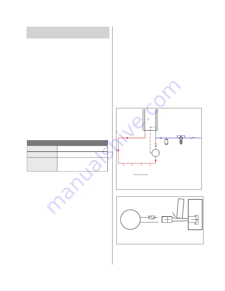
Plumbing Diagram
PUMP
Cut
w
ire
to
co
nne
ct
to p
ump
PC
Board
4 Amp
Fuse
Cut connector and
splice
BL
W
Pump Electrical Connection
Hot Water
Supply Line
(minimum 3/4 in.)
Electrical
Connection
(Power)
Recirculation Loop
Pump
Hot Water Outlets
Return Line
(minimum 3/4 in.)
Check Valve
(required)
Thermal
Expansion Tank
Rinnai
Scale
Control
(recommended)
Cold Water Supply Line
Check Valve


