background image

 62 


Rinnai Tankless Water Heater Installation and Operation Manual

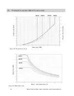
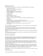
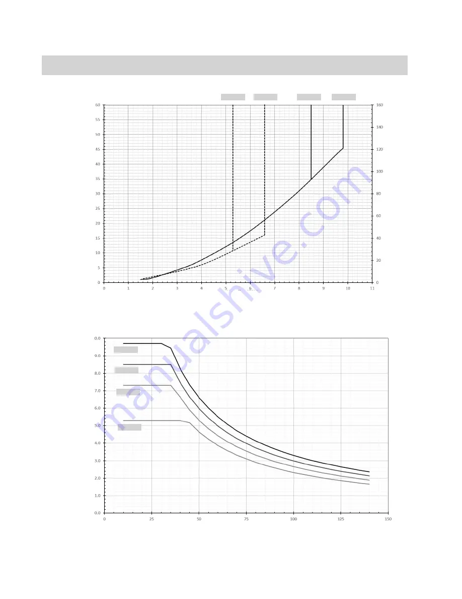
7.4  Pressure Drop and Water Flow Curves

Pressure Loss (PSI)

Water Flow (GPM)

Presure Loss (ft of Head)

RE160

RE180

RE199

Figure 52: Pressure Drop Curve

Figure 53: Water Flow Curve

RE140

W

ater Flow (GPM)

Delta T - Temperature Rise (

°F)

RE140

RE160

RE180

RE199

Summary of Contents for RE140e

Page 1: ...U VE2432WD US VE160e REU VE2125WD US VE140e REU VE1720WD US Tankless Water Heater Installation and Operation Manual ANSI Z21 10 3 CSA 4 3 INDOOR MODELS RE199i REU VE2737FFD US RE180i REU VE2432FFD US...

Page 2: ...not use any phone in your building Immediately call your gas supplier from a neighbor s phone Follow the gas supplier s instruc tions If you cannot reach your gas supplier call the fire department Ins...

Page 3: ...allation Guidelines 15 4 2 What You Will Need 16 4 3 Choose an Installation Location 17 4 4 Mount the Water Heater to the Wall 22 4 5 Vent the Water Heater 24 4 6 Connect Water Supply 32 4 7 Install P...

Page 4: ...intenance 53 6 1 Maintenance 53 6 2 Flushing the Heat Exchanger 56 6 3 Draining the Water Heater 57 7 Appendices 58 7 1 Massachusetts State Gas Regulations 58 7 2 Wiring Diagram 60 7 3 Ladder Diagram...

Page 5: ...used in this manual Thank you for purchasing a Rinnai Tankless Water Heater Before installing and operating this water heater be sure to read these instructions completely and carefully to familiariz...

Page 6: ...Indicates a potentially hazardous situation which if not avoided will result in personal injury or death The following precautions apply to the trained and qualified professional and consumer Read and...

Page 7: ...f the control system and any manual gas control valve which has been under water DO NOT use substitute materials Use only parts certified for the appliance Should overheating occur or the gas sup ply...

Page 8: ...tandBottomView Indoor Outdoor Figure 1 Front view Hot Water Outlet Cold Water Inlet Gas Inlet Cold Water Inlet Gas Inlet Hot Water Outlet Figure 2 Bottom view Topics in this section Front and Bottom V...

Page 9: ...Ignition Unit PC Board Controller removed for clarity Heat Exchanger Figure 3 Main Components Fan Motor Assembly Condensate Drain indoor models only Concentric 3 in Exhaust 5 in Combustion Air indoor...

Page 10: ...Fixed Bypass Bypass Servo Control Fixed Bypass Gas Supply Pressure 2 Natural Gas 4 0 in wc 10 5 in wc Propane 8 0 in wc 13 0 in wc Type of Appliance High Efficiency Non condensing Tankless Temperature...

Page 11: ...sions Figure 5 Outdoor Dimensions Indoor Models RE199i RE180i RE160i and RE140i Outdoor Models RE199e RE180e RE160e and RE140e Front View Side View Front View Side View 2 64 67 22 87 581 24 64 626 14...

Page 12: ...3 4 MNPT H Hot Outlet 4 6 117 5 82 148 4 76 120 3 4 MNPT B Bracket 40 10 1 6 41 0 59 15 N A 3 4 1 Supply Connections Measurements in mm Figure 7 Outdoor Model Supply Connections Table 3 Supply Connect...

Page 13: ...the water heat er for aesthetic purposes control r Wi Fi Module And Accessories Part RWM101 Controls On Demand recirculation remotely adjust temperatures and com municates with the Pro Portal The con...

Page 14: ...Return Valve Part 107000450 Valve kit including tee drain valve check valve and isolation valve to simplify set up of a dedicated recirculation line Wall Mounting Bracket Part 109000628 Optional acce...

Page 15: ...s or in the absence of local codes with the National Electrical Code ANSI NFPA 70 or the Canadian Electrical Code CSA C22 1 The appliance and its manual gas shutoff control valve must be disconnected...

Page 16: ...T use substitute parts that are not authorized for this appliance DO NOT run the unit with the front cover removed during normal operation 4 2 WhatYouWill Need 4 2 1 Items Included Unpack the Rinnai T...

Page 17: ...it This water heater also includes a service indicator Service Soon SS When selected in the parameter settings an SS code will display on the controller indicating that it is time to flush and service...

Page 18: ...ater heaters Where possible install internal indoor water heaters in a sealed closet so that it is protected from the potential of contaminated indoor air 4 3 4 Outdoor Water Heaters and Vent Terminat...

Page 19: ...manually However it is highly recommended to install the optional Drain Down Kit accessory that will enable the water heater to immediately drain upon loss of power the pressure relief valve is not af...

Page 20: ...ust 24 in 610 mm Indoor internal units Outdoor external units Top Side If clearances are not met damage to the property and water heater may occur Location Clearances To Combustibles and Non Combustib...

Page 21: ...or combustion The water supply does not contain chemicals or exceed total hardness that will damage the heat exchanger A standard 3 prong 120 V AC 60 Hz properly grounded wall outlet for indoor models...

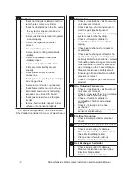
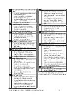
Page 22: ...ts Use a level placed horizontally or vertically to make sure the water heater is straight Proper operation requires the water heater to be level Make sure the securing method is sufficient to support...

Page 23: ...with the wall Use any of the holes in the top and bottom brackets Use a level placed horizontally or vertically to make sure the water heater is straight Proper operation requires the water heater to...

Page 24: ...tight seal Follow the venting manufacturer s instructions The vent piece connected to the water heater must be secured with 1 self tapping screw Refer to the instructions of the vent system manufactu...

Page 25: ...it that may result in exhaust gases entering the soffit vent Install vent termination such that exhaust and rising moisture will not collect under eaves Discoloration to the exterior of the building c...

Page 26: ...00 772 0739 www heatfab com Metal Fab 800 835 2830 www metal fabinc com Table 8 Approved Vent Manufacturers Table 9 Approved Vent Products Manufacturer Manufacturer Part number Product Description Dia...

Page 27: ...on public property Vents for Category II and IV appliances cannot be located above public walkways or other areas where condensate or vapor can cause a nuisance or hazard M Clearance under veranda por...

Page 28: ...n cold climates If more than one elbow is used in the vertical section the condensate collector must be used Slope the venting 1 4 in per foot toward the appliance according to the vent manufacturers...

Page 29: ...th must be at least the same diameter as the drain line 5 8 inch The end of the condensate drain pipe should be open to the atmosphere The end should not be under water or other substances To minimize...

Page 30: ...0 ft 3 m horizontally L Clearance above paved sidewalk or paved driveway located on public property Vents for Category II and IV appliances cannot be located above public walkways or other areas where...

Page 31: ...m Parameter Setting 2A Refer to section 4 10 1 Configure Parameter Settings for specific details on setting parameters Altitude Parameter Setting 0 2 000 ft 0 610 m 02A 2 001 5 400 ft 610 1 646 m 02b...

Page 32: ...intended to describe a complete system It is up to the contractor engineer to determine the necessary components and configuration of the particular system being installed This drawing does not imply...

Page 33: ...lve is connected below the appliance DO NOT place any other valve or shut off device between the pressure relief valve and the water heater If a pressure relief valve discharges periodically this may...

Page 34: ...pecifications with all gas appliances operating Install a proper gas regulator upstream of a water heater if a supply gas pressure is too high 4 Before placing the appliance in operation all joints in...

Page 35: ...appropriate table from the applicable code must be used Table 13 Gas Pipe Sizing Calculation Worksheet Instructions Enter values in empty boxes Rinnai Model Gas Input Additional Appliance Total Gas I...

Page 36: ...160 336 632 1 300 40 12 137 287 541 1 110 50 15 122 255 480 985 60 18 110 231 434 892 80 24 101 212 400 821 100 30 94 197 372 763 Schedule 40 Metallic Pipe Inlet Pressure 11 in wc Specific Gravity 1...

Page 37: ...60 Hz properly grounded wall outlet On external outdoor models a proper disconnect i e on off switch power cord etc must be provided and installed for the incoming 120 V AC power The switch should be...

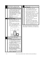
Page 38: ...he two push buttons A and B on the PC Board 3 Press the A button for 1 second 4 Use the Up and Down buttons on the controller to select a setting number see Parameter Settings Table below 5 Once the d...

Page 39: ...g Short Table 18 Parameter Settings Table RE140 does not have recirculation mode This water heater includes a service indicator Service Soon SS When selected in the parameter settings an SS code will...

Page 40: ...y by unplugging the power cord or by turning off the electricity at the circuit breaker 2 Install the recirculation pump on the return line according to the pump manufacturer installation instructions...

Page 41: ...ation PLUMBING YES NO Have the water lines been purged of all debris and the filter cleaned Have you verified the hot and cold water lines to the tankless water heater are not interchanged Does the wa...

Page 42: ...PRV discharge line from freezing Have you verified the PRV is not plugged and that reducing fittings valves or other restrictions are not installed in the relief line GAS SUPPLY YES NO Did you verify...

Page 43: ...t of the control system and any gas control which has been under water Should overheating occur or the gas supply fail to shut off turn off the manual gas shut off control valve to the appliance Use o...

Page 44: ...ervice technician or gas supplier TURN OFF GAS TO APPLIANCE 1 Set the temperature controller to lowest setting 2 Turn off all electric power to the appliance if service is to be performed 3 Turn the m...

Page 45: ...e the beeps when keys are pressed press and hold both the Up and Down buttons at the same time until a beep is heard approximately 5 seconds Then release both buttons To turn on the beeps repeat the a...

Page 46: ...e water heater is off press the On Off button to turn on 2 If multiple controllers are installed the Priority button when selected will enable that controller to function Note Priority can only be cha...

Page 47: ...e is 185 F water pressure should be between 45 and 150 PSI 5 5 PerformanceData To obtain performance data 1 Press and hold the Down button 2 While holding the Down button for 2 seconds press and hold...

Page 48: ...Current x10 mA 10 Total Bath Fill Amount Gallons 1 1 HEX Outlet Temp F 12 By Pass Flow Control Position Degrees of opening 14 Intake Thermistor Temperature Indoor Units Only F 17 Freeze Protection Te...

Page 49: ...st Check all vent components for proper connections Ensure vent length matches with the vent lengths set in the parameter settings Verify High Altitude setting are set properly See Parameter Setting C...

Page 50: ...gas type being used Check for low water flow in a circulating system causing short cycling Check for foreign materials in combustion chamber and exhaust piping Check heat exchanger for cracks or separ...

Page 51: ...age Measure resistance of sensor Ensure fan blade is tight on motor shaft and is in good condition Replace sensor if necessary 41 Freeze Protection Thermistor Check sensor wiring for damage Measure re...

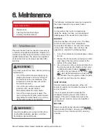
Page 52: ...ging the SS indicator SS indicates that it is time for service The heat exchanger should be flushed to prevent damage refer to section 6 2 Flushing the Heat Exchanger for more information Hard water m...

Page 53: ...our water heater CLEANING It is imperative that control compartments inside the cabinet burners and circulating air passageways of the appliance be kept clean BURNER Check burner flame for proper colo...

Page 54: ...ion air or exhaust vent pipes are blocked or partially blocked by obstructions Keep the condensate drain line free of snow and ice Ensure the line is not blocked or clogged and that condensate is flow...

Page 55: ...No liability is assumed for any issues resulting from the use of this information Note See section 6 3 Draining the Water Heater for detailed instructions on Draining the water heater Running a low v...

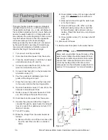
Page 56: ...ose H2 to the pump inlet into the cleaning solution 8 Open both isolation valves V1 and V2 on the hot water and cold water lines 9 Restore power to the water heater for 20 30 sec this will open the wa...

Page 57: ...ose the hot and cold drain valves 3 Open the cold and hot water isolation valves 4 Connect power to the water heater and tighten the inlet water filter 5 Open a tap and confirm that water flows and th...

Page 58: ...ng building or structure served by the side wall horizontal vented gas fueled equipment It shall be the responsibility of the property owner to secure the services of a trained and qualified professio...

Page 59: ...cturer s recommendations Tempered water to plumbing fixtures Must meet temperature requirements of 248 CMR Hot Water Supply and Return to Heating Coil Electronically controlled pump timer Activates ev...

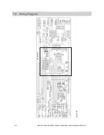
Page 60: ...60 Rinnai Tankless Water Heater Installation and Operation Manual 7 2 WiringDiagram Figure 50 PC Board...

Page 61: ...Rinnai Tankless Water Heater Installation and Operation Manual 61 7 3 LadderDiagram Figure 51...

Page 62: ...ration Manual 7 4 PressureDropandWaterFlowCurves Pressure Loss PSI Water Flow GPM Presure Loss ft of Head RE160 RE180 RE199 Figure 52 Pressure Drop Curve Figure 53 Water Flow Curve RE140 Water Flow GP...

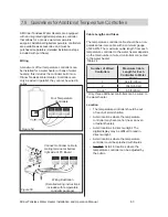
Page 63: ...m cable length from each temperature controller to the water heater depends on the total number of wired controllers connected to the water heater Number of Wired Controllers Maximum Cable Length for...

Page 64: ...t is defective in materials or workmanship as set forth in the above table Rinnai will pay reasonable labor charges associated with the repair or replacement of any such part or component during the t...

Page 65: ...71 C This Limited Warranty does not apply to any product whose serial number or manufacture date has been defaced This Limited Warranty does not cover any product used in an application that uses chem...

Page 66: ...100000722 02 12 2021 Rinnai America Corporation 103 International Drive Peachtree City GA 30269 Tel 1 800 621 9419 Web rinnai us rinnai ca...

Reviews: