34
2.6 INSTALLATION
2.6.1 HyDRAULIC COUpLINGS
IMPORTANT
Before proceeding with the hydraulic couplings, a good cleaning of the thermal installation is
necessary (pipes, heating elements, etc.) to not compromise the product warranty. It must be done
with specific pickling or anti-scaling products which are able to remove eventual residuums that
could affect the good functioning of the product.
The DPR 59/09 prescribes a chemical treatment for the water used by the thermal installation,
according to the UNI 8065 standard, in the cases covered by the Ordinance, and in order to protect
the installation and the device from pipe-scaling, mud and other dangerous deposits.
The dimensioning and the layout of hydraulic pipes must be properly designed in order to ensure an adequate water
flow rate to the appliance.
Domestic hot water
The DHW connections are: 15A (R1/2”) male type.
Where the water supply pressure exceeds 10bar, an approved pressure regulator must be fit at the inlet of the
appliance. To achieve the maximum flowrate, a water supply pressure of 1.5bar is required. The unit will operate
at lower pressures but the maximum flow rate may not be achieved. The minimum pressure to ensure the nominal
flowrate is equal to: 0.7Bar (Zen I24), 1.10Bar (Zen I29), 1.2Bar (Zen I34).
Connect the hot and cold water supply pipes. An approved interception ball valve and strainer MUST be installed on
the cold water inlet pipe. An approved interception ball valve and draining point should be installed on the hot water
outlet pipe. Do not connect the valves directly to the appliance, but interpose a flexible connection joint.
If the boiler is installed in a hard water area, a suitable water conditioning system must be installed to prevent limescale
damages to the heat exchanger: damages by scaling are not covered by the manufacturer’s warranty. Below are some
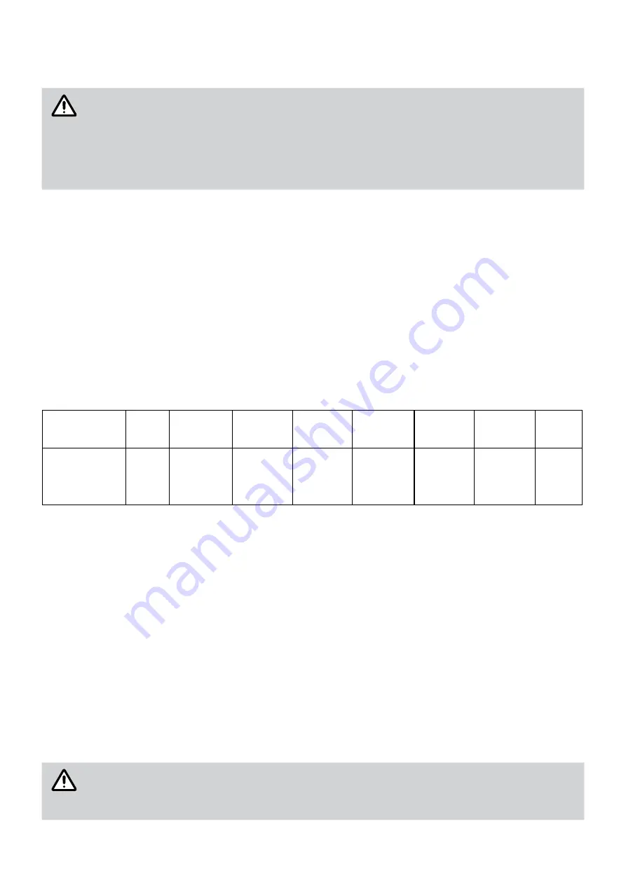
limit values of substances dissolved in water:
Description
pH
Tot.
dissolved
solid
Total
hardeness
Chlorides Magnesium
Calcium
Sodium
Iron
Maximum
recommended
levels
6.5-9.0
600mg/liter
150mg/liter
300mg/liter
10mg/liter
20mg/liter
150mg/liter 1mg liter
The hydraulic pipes must be insulated to optimize energy efficiency and reduce heat loss.
Heating
The CH connections are: 20A (PT3/4”) male type.
The vent valve must be connected to an exhaust funnel and conveyed appropriately to prevent damages.
When connecting the water supply pipes, it is recommended to have an interception ball valve and a filter on the return
pipe from the system, and an interception ball valve on the flow connection. Do not connect the valves directly to the
boiler, but interpose a flexible connection joint. It is recommended the installation of vent valves on the system.
Condensate drain pipe
During operation, the appliance can produce a significant amount of condensate as a product of the combustion of a
highly-efficient system. The condensate is mild acid and non-potable: to prevent damages and disposal problems, the
boiler is equpped with a sealed condensate trap siphon, already filled with an acid-neutraliser (the duration fo use is
estimated to be eight/ten year long - it is necessary to check the PH regularly).
Connect a non-metallic pipe to the siphon’s base (PVC, PVC-U, ABS, PVC-C or PP): it drains and eliminates excess of
condensate. The connected pipe must have minimum slope of 2.5°. It is recommended to install the condensate drain
pipe indoor to prevent freezing; if it is installed outside, it must be connected to a tube of Ø≥32mm and an adequate
protection against frost must be provided to the pipe.
IMPORTANT
Once the condensate drain is connected, proceed with filling the siphon by pouring water into
the exhaust duct until the siphon is overflowed: pay attention to this phase because a siphon that
is not correctly filled can spread harmful combustion products into the room where the boiler is
installed.


