50
3.3 GAS CONVERSION AND PRESSURE ADJUSTMENT
This procedure can only be performed by qualified technical personnel.
Any tampering by unqualified personnel will result in immediate forfeiture of the product warranty.
The gas valve assembly and the electronic board are electronically calibrated at the factory during
product testing.
The appliance does NOT need to be adjusted during installation.
The conversion procedure to a different type of gas consists of three phases:
1.
modification of the microswitches of the electronic board and selection of the new type of gas;
2.
gas nozzle replacement;
3.
verification of CO
2
and possible regulation of gas pressure (at minimum and maximum forced regime).
phase 1
•
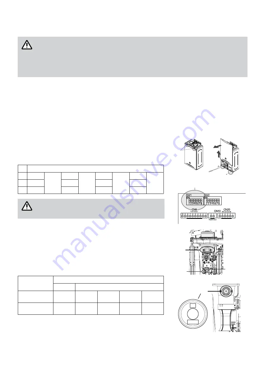
Close the gas supply valve and disconnect the plug from the socket;
•
remove the front panel;
•
verify that the type of gas selected by the microswitches of the bank
SW1 coincides with the gas used in the system:
Nr.
SW1
1
OFF
NG
(G20)
ON
Prop.
(G31)
OFF
Air-
prop.
(G230)
ON
LPG
(G30)
2
OFF
OFF
ON
ON
3
OFF
OFF
OFF
OFF
The specific procedure described in PCB paragraph
must be followed, in order to make any change to the
microswitches effective.
phase 2
•
Disconnect the gas valve supply cable;
•
unscrew the screws (3x) that fix the gas valve;
•
remove the valve taking care not to damage the sealing O-rings;
•
replace the gas nozzle:
Model
Letter mark
A
B
REB-KBI2424FF
REB-KBI2929FF
29
G20
G30
G31
G230
REB-KBI3535FF
35
G20
G30
G31
G230
•
assemble the gas valve taking care not to damage the o-rings;
•
open the gas supply valve and check that there are no gas leaks from
the circuit.
ATTENTION
Latches
Main electronic board
Remove the front panel
Dip switches SW1
①
②
ATTENTION
Screw (2x)
Screw
Gas valve
Gas nozzle
Nozzle
Power cable
A
B


