Infinity REU-2425W
- 8 -
Issue 2 - 5/07/04 ©Rinnai
Connecting remote control cables
Do not attempt to connect the remote control cable terminals to the appliance with the
power on.
RISK OF ELECTRICAL SHOCK
Connecting One or Two Controllers
1. Isolate the power supply.
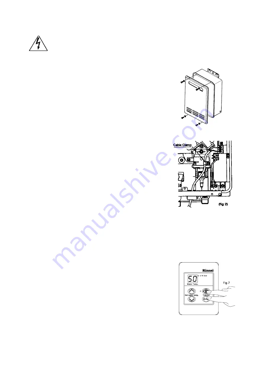
2. Remove the front cover from the Appliance (4 screws) fig. 1.
3. Thread the cable(s) through the cable access hole at the base of
the appliance.
4. Locate the terminals for controls, the position of which is marked on
the Printed Circuit Board casing. Connect the space connectors to
the terminals on the P.C.B. (Fig. 2). Polarity is not important. Either
wire colour can be connected to either terminal.
5. Replace cover of the Appliance. Ensure that the special screw is
placed at the bottom right hand corner for earthing purposes.
Connecting Three Controllers
1. Isolate the power supply.
2. Remove the front cover from the Appliance (4 screws) fig.1.
3. Cut the spade connectors from 2 of the controller cables to be
connected to the appliance (4 spade connectors should be cut off)
and discard. Connect the wires from these two cables and
terminate into two new spade connectors as shown in fig.3. Spade
connectors are available from your local electrical component
retailer.
4. Located the terminals for controls, the position of which is marked
on the Printed Circuit Board casing. Connect the 4 spade
connectors to the terminals on the P.C.B. (Fig. 2). Polarity is not
important. Either wire colour can be connected to either terminal.
5. Replace cover of the Appliance. Ensure that the special screw is
placed at the bottom right hand corner for earthing purposes.
MC-91A Controller Programming
Is there a label on the appliance casing that contains the text.
“THIS APPLIANCE DELIVERS WATER NOT EXCEEDING 50° C
IF YES:No further action required.
IF NO: You will need to program Kitchen controller to enable selection of
temperatures higher than 50º C.
STEP 1:
For the controller in the KITCHEN only, press and hold the 'Transfer'
and 'On/Off' buttons simultaneously (see Fig 7.) until a 'beep' is heard
(approximately 5 seconds).
STEP 2:
When the controller fitted in the KITCHEN is switched on, it should be
possible to select temperatures higher than 50º C. If not, repeat Step 1.
Note:
• If the kitchen controller is replaced, repeat STEP 1 above for the replacement controller.
• If the kitchen controller is swapped with another controller (for example, the controller fitted in a
bathroom), repeat STEP 1 for the controller moved from the kitchen to the bathroom. Then perform
STEP 1 for the controller moved from the bathroom to the kitchen.
fig.1.
Summary of Contents for REU-2018W
Page 8: ...Infinity REU 2425W 5 Issue 2 5 07 04 Rinnai 3 Dimensions Note All dimensions are in mm ...
Page 14: ...Infinity REU 2425W 11 Issue 2 5 07 04 Rinnai 7 Cut away Diagram ...
Page 15: ...Infinity REU 2425W 12 Issue 2 5 07 04 Rinnai 8 Schematic Diagram ...
Page 33: ...Infinity REU 2425W 30 Issue 2 5 07 04 Rinnai 20 Wiring Diagram ...
Page 54: ...Infinity REU 2425W 51 Issue 2 5 07 04 Rinnai 26 Exploded Diagram ...
Page 55: ...Infinity REU 2425W 52 Issue 2 5 07 04 Rinnai ...
Page 56: ...Infinity REU 2425W 53 Issue 2 5 07 04 Rinnai ...
Page 57: ...Infinity REU 2425W 54 Issue 2 5 07 04 Rinnai ...
Page 60: ...Infinity REU 2425W Issue 1 5 07 04 Rinnai Notes ...


