Infinity REU-2425W
- 48 -
Issue 2 - 5/07/04 ©Rinnai
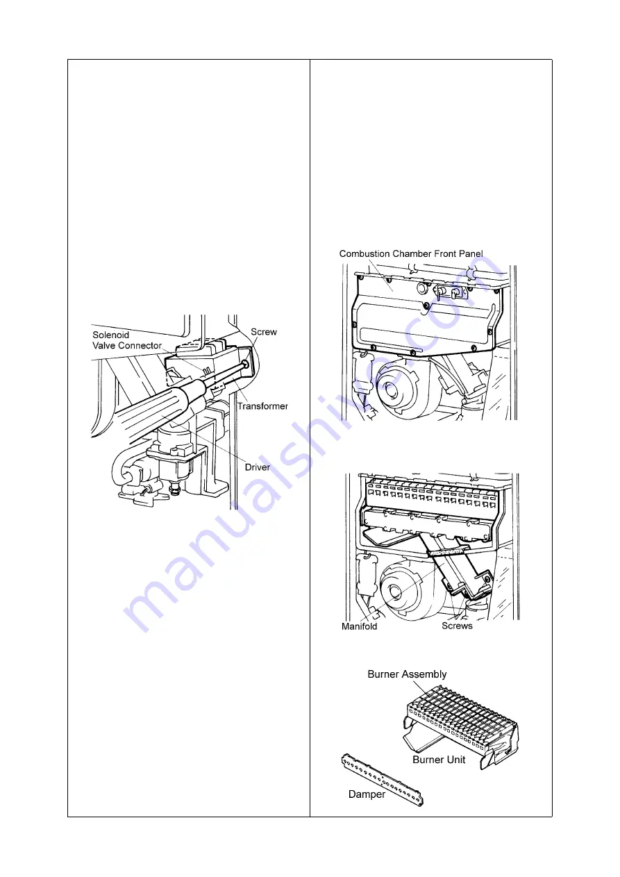
9) Removal of Transformer
CAUTION
- 240 volt potential exposure. Isolate the
appliance and reconfirm with a neon
screwdriver or multimeter.
a. Remove the PCB unit; refer to section 2.
b. Remove the sparker; refer to section
4.
c.
Remove one solenoid valve
connector.
d. Remove two (2) fixing screws to
release the transformer (phillips
driver)
e. Disconnect connectors.
10) Removal of Manifold and Burner
CAUTION
- 240 volt potential exposure. Isolate the
appliance and reconfirm with a neon
screwdriver or multimeter.
a. Remove the sparker, refer section 4.(1 screw)
b. Remove eleven (11) screws that hold
the combustion chamber front panel
in place and remove the panel
(phillips driver)
c.
Remove the five (5) screws that
secure the manifold in place and pull
out the manifold (phillips driver).
d. Pull burner unit forward to remove
(hand)
Summary of Contents for REU-2018W
Page 8: ...Infinity REU 2425W 5 Issue 2 5 07 04 Rinnai 3 Dimensions Note All dimensions are in mm ...
Page 14: ...Infinity REU 2425W 11 Issue 2 5 07 04 Rinnai 7 Cut away Diagram ...
Page 15: ...Infinity REU 2425W 12 Issue 2 5 07 04 Rinnai 8 Schematic Diagram ...
Page 33: ...Infinity REU 2425W 30 Issue 2 5 07 04 Rinnai 20 Wiring Diagram ...
Page 54: ...Infinity REU 2425W 51 Issue 2 5 07 04 Rinnai 26 Exploded Diagram ...
Page 55: ...Infinity REU 2425W 52 Issue 2 5 07 04 Rinnai ...
Page 56: ...Infinity REU 2425W 53 Issue 2 5 07 04 Rinnai ...
Page 57: ...Infinity REU 2425W 54 Issue 2 5 07 04 Rinnai ...
Page 60: ...Infinity REU 2425W Issue 1 5 07 04 Rinnai Notes ...


