background image


V53e Outdoor Manual 

21 


Water 

Piping 


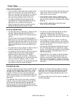
The freeze protection features include electrical heating 
elements and intermittent firing of the burner.  Freeze 
protection may be disabled if electricity or gas is not 
supplied, or if there is an error preventing the water 
heater from functioning.  Loss of freeze protection may 
result in water damage from a burst heat exchanger or 
water lines. 

The installation of auto drain down solenoid valves is 
optional.  However, Rinnai strongly recommends that 
these valves be installed to prevent damage from 
freezing in case the normal freeze protection should 
become disabled.  Any product damage due to freezing 
will not be covered by the warranty. 

In addition, the solenoid valves should be connected 
electrically to a sub-PC board that attaches to the PC 
board in the unit.  This allows the solenoid valves to 
operate if the water heater is disabled due to an error 
code.   

The solenoid valves and sub-PC board are available for 
purchase separately. 


Freeze Protection 

• 

A manual water control valve must be placed in the 
water inlet connection to the Rinnai water heater 
before it is connected to the water line.  Unions may 
be used on both the hot and cold water lines for 
future servicing and disconnection of the unit. 

• 

The piping (including soldering materials) and 
components connected to this appliance must be 
approved for use in potable water systems. 

• 

Purge the water line to remove all debris and air.  
Debris will damage the Rinnai water heater. 

• 

Toxic chemicals such as those used for boiler water 
treatment are not to be introduced to the potable 
water used for space heating. 

• 

If the appliance will be used as a potable water 
source, it must not be connected to a system that 
was previously used with a nonpotable water heating 
appliance. 

• 

Ensure that the water filter on the Rinnai water 
heater is clean and installed. 

• 

An approved pressure relief valve is required by the 

American National Standard (ANSI Z21.10.3) / 
Canadian Standard (CSA 4.3) 

for all water heating 

systems. 

• 

The relief valve must comply with the standard for 

Relief Valves and Automatic Gas Shutoff Devices for 
Hot Water Supply Systems ANSI Z21.22

 and /or the 

standard 

Temperature, Pressure, Temperature and 

Pressure Relief Valves and Vacuum Relief Valves, 
CAN1-4.4

.   

• 

The relief valve must be rated up to 150 psi and to at 
least the maximum BTU/hr of the appliance. 

• 

The discharge from the pressure relief valve should 
be piped to the ground or into a drain system to 
prevent exposure or possible burn hazards to 
humans or other plant or animal life.  Follow local 
codes.  Water discharged from the relief valve could 
cause severe burns instantly, scalds, or death. 

• 

The pressure relief valve must be manually operated 
once a year to check for correct operation. 

• 

The relief valve should be added to the hot water 
outlet line according to the manufacturer’s 
instructions.  DO NOT place any other type valve or 
shut off device between the relief valve and the water 
heater. 

• 

Do not plug the relief valve and do not install any 
reducing fittings or other restrictions in the relief line.  
The relief line should allow for complete drainage of 
the valve and the line. 

• 

If a relief valve discharges periodically, this may be 
due to thermal expansion in a closed water supply 
system.  Contact the water supplier or local plumbing 
inspector on how to correct this situation.  Do not 
plug the relief valve. 

• 

Neither Rinnai nor the 

American National Standard 

(ANSI Z21.10.3) / Canadian Standard (CSA 4.3) 

requires a combination temperature and pressure 
relief valve for this appliance.  However, local codes 
may require a combination temperature and pressure 
relief valve. 

Pressure Relief Valve 

General Instructions 

Summary of Contents for REU-VAM1620W

Page 1: ...r service agency or the gas supplier WARNING If the information in these instructions is not followed exactly a fire or explosion may result causing property damage personal injury or death Operation and Installation Manual INSTALLER Leave this manual with the appliance CONSUMER Retain this manual for future reference Table of Contents 2 Consumer Safety Information 4 Operating Instructions 5 Maint...

Page 2: ...hooting for Common Issues 15 Accessing Operating Information with a Remote Controller 15 Water Quality 15 Flushing the Heat Exchanger 16 Error Code LC or 00 Installation Instructions 17 General Instructions 17 Clearances from Appliance 18 Attachment of the Water Heater 18 Electrical Connection 19 Gas Piping General Instructions 19 Pipe Sizing Procedure Example 20 Water Piping General Instructions ...

Page 3: ...ntinuous flow gas hot water system for residential applications Operation With or without remote controls mounted in kitchen bathroom etc Approved Gas Type Natural Gas or Propane Ensure unit matches gas type supplied at the installation location Connections Gas Supply 3 4 MNPT Cold Water Inlet 3 4 MNPT Hot Water Outlet 3 4 MNPT Ignition System Direct Electronic Ignition Electric Connections Applia...

Page 4: ...e will automatically shut down if the burner flame is extinguished Power Failure The appliance will cut off the gas if it loses electrical power Power Surge Fuse A glass fuse protects against overcurrent If the fuse blows then all indicator lamps will be off Fusible Link In case the overheat feature does not prevent the temperature from rising then the fusible link will break shutting off the appl...

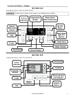
Page 5: ...dicator Indicates that this controller is setting the temperature Priority can be switched to another controller by pressing its Priority Button when no hot water is running Sound Volume Used to adjust the voice prompt volume Temperature Display Shows the temperature setting Thermostat Increases or decreases the temperature setting Water Smart Bath Fill Button Indicator Used to select the Water Sm...

Page 6: ...n ON OFF Button MC 91 1US MC 502RC 1US S Wireless Requires the transceiver MC 502RC 1US M to be connected to the water heater Refer to the MC 502RC 1US S manual and the Wireless Controller Installation Instructions for complete details on features operation and installation Dimensions inches 3 5 W x 4 75 H x 0 75 D Dimensions inches 4 33 W x 5 90 H x 1 16 D The MC 91 controller allows a maximum te...

Page 7: ...tton In Use Indicator Clock Call Priority Button and Indicator Water Smart Bath Fill Indicator Water Smart Bath Fill Button Power Save Water Volume Sound Volume MC 100V 1US BC 100V 1US The BC 100V controller is water resistant Avoid splashing the controller NOTICE Remote Controllers Models Dimensions inches 5 0 W x 4 75 H x 0 75 D Dimensions inches 8 0 W x 4 125 H x 0 875 D ...

Page 8: ... setting All hot water sources are able to provide water at this temperature setting until it is changed again at this or another remote controller Check local codes for the maximum water temperature setting allowed when used in nursing homes schools day care centers and all other public applications NOTICE If a newly installed unit with a remote controller has not been powered for at least 6 hour...

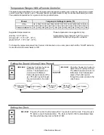
Page 9: ...t on the MC 100V Suggested temperatures are Kitchen 120 ºF 49º C Shower 98º 110º F 37º 43º C Bath Fill 102º 110º F 39º 43º C These temperatures are suggestions only A temperature lower than 98º F 37º C can be obtained at the tap by mixing with cold water To change the temperature scale from Celsius to Fahrenheit or vice versa press and hold the On Off button for 5 seconds while the water heater is...

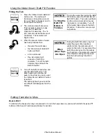
Page 10: ... water heater will stop the hot water flow when the preset volume has been reached The hot water tap should then be closed and the bath fill button pressed The temperature settings for the bath fill function are limited to those in the table below Power Loss If power is lost during the bath fill function the water heater will shut down but the water will continue to flow When power returns the wat...

Page 11: ...ess the Water Smart Bath Fill button The button will flash and the voice prompt will announce Hot water is not available Turn off all hot water taps and push the Bath Fill button Follow the voice prompt instructions NOTICE the water flow will cease the Water Smart Bath Fill button will flash a tone will sound the voice prompt will announce Bath fill is complete Turn off the bath hot water tap and ...

Page 12: ... Air Intake and Exhaust The air intake and exhaust should be inspected at least annually for blockages or damage Motors Motors are permanently lubricated and do not need periodic lubrication Keep fan and motor free of dust and dirt by cleaning annually Remote Controller Use a soft damp cloth to clean the remote controller Do not use solvents Lime Scale Buildup If you receive Error Code LC refer to...

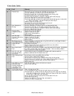
Page 13: ...pect burner surface for condensation or debris 12 Flame Failure Check that the gas is turned on at the water heater and gas meter Check for obstructions in the flue outlet Ensure gas line meter and or regulator is sized properly Ensure gas type and pressure is correct Bleed all air from gas lines Verify dip switches are set properly Ensure appliance is properly grounded Disconnect keypad Disconnec...

Page 14: ...Fan Failure Ensure fan will turn freely Check wiring harness to motor for damaged and or loose connections Measure resistance of motor winding 65 Water Flow Control Fault The water flow control valve has failed to close during the bath fill function Immediately turn off the water and discontinue the bath fill function Contact a state qualified or licensed contractor to service the appliance 71 SV0...

Page 15: ...er continues to run The fan is designed to continue running for a short time after the flow of water stops This is to ensure constant water temperatures during rapid starting and stopping as well as exhausting any residual gas flue products from the unit Consideration of care for your water heater should include evaluation of water quality If the water quality exceeds the target levels provided in...

Page 16: ...water and cold water lines V3 and V4 3 Connect pump outlet hose H1 to the cold water line at service valve V2 4 Connect drain hose H3 to service valve V1 5 Pour approximately 4 gallons of virgin food grade white vinegar or citric acid into pail 6 Place the drain hose H3 and the hose H2 to the pump inlet into the cleaning solution 7 Open both service valves V1 and V2 on the hot water and cold water...

Page 17: ...re testing of that system at test pressures in excess of 1 2 psi 3 5 kPa 13 84 in W C The appliance must be isolated from the gas supply piping system by closing its individual manual shutoff valve during any pressure testing of the gas supply piping system at test pressures equal to or less than 1 2 psi 3 5 kPa 13 84 in W C Follow the installation instructions and those in the Maintenance section...

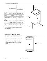
Page 18: ...ent to support the weight Refer to the weight of the water heater in the Specifications section Attachment of the Water Heater wall installation brackets to Combustibles to Non Combustibles Top of Heater 12 inches 305 mm 2 inches 51 mm Back of Heater 0 zero 0 zero Front Panel 24 inches 610 mm 0 inches 0 mm Sides of Heater 6 inches 152 mm 1 8 inch 3 2 mm Floor Ground 12 inches 305 mm 2 inches 51 mm...

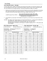
Page 19: ... to the water heater The gas supply line shall be gas tight sized and so installed as to provide a supply of gas sufficient to meet the maximum demand of the heater and all other gas consuming appliances at the location without loss of pressure Any compound used on the threaded joint of the gas piping shall be a type which resists the action of liquefied petroleum gas propane LPG Refer to an appro...

Page 20: ...able Propane Gas Pipe Size inches 3 4 1 1 1 4 1 1 2 10 273 514 1060 1580 20 188 353 726 1090 30 151 284 583 873 40 129 243 499 747 50 114 215 442 662 60 104 195 400 600 70 95 179 368 552 80 89 167 343 514 90 83 157 322 482 100 79 148 304 455 125 70 131 269 403 150 63 119 244 366 175 58 109 224 336 200 54 102 209 313 Length Length Pipe Size inches 1 2 3 4 1 1 1 4 10 291 608 1150 2350 20 200 418 787...

Page 21: ...onpotable water heating appliance Ensure that the water filter on the Rinnai water heater is clean and installed An approved pressure relief valve is required by the American National Standard ANSI Z21 10 3 Canadian Standard CSA 4 3 for all water heating systems The relief valve must comply with the standard for Relief Valves and Automatic Gas Shutoff Devices for Hot Water Supply Systems ANSI Z21 ...

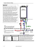
Page 22: ...mpliance with local building code requirements It is the responsibility of the contractor engineer to ensure installation is in accordance with all local building codes Confer with local building officials before installation Freeze Protection Piping Warranty does not cover damage due to freezing With electrical power and gas supplied to a Rinnai water heater it will not freeze in environments as ...

Page 23: ...ating Pump Solenoid Valve Boiler Drain Valve KEY This is not an engineered drawing It is intended only as a guide and not as a replacement for professionally engineered project drawings This drawing is not intended to describe a complete system It is up to the contractor engineer to determine the necessary components and configuration of the particular system being installed This drawing does not ...

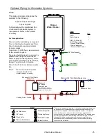
Page 24: ...ater and supply and return plumbing Reference the Rinnai Hot Water System Design Manual Pump Sizing for Circula tion Pump to be of bronze or stainless construction This is not an engineered drawing It is intended only as a guide and not as a replacement for professionally engineered project drawings This drawing is not intended to describe a complete system It is up to the contractor engineer to d...

Page 25: ... is recommended for the circulation system The pump should be sized to overcome the pressure loss through the Rinnai water heater supply and return plumbing Refer ence the Rinnai Hot Water System Design Manual Pump Sizing for Circulation Pump to be of bronze or stainless construc tion This is not an engineered drawing It is intended only as a guide and not as a replacement for professionally engin...

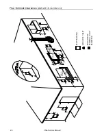
Page 26: ...Outdoor Manual Flue Terminal Clearances ANS Z21 10 3 CSA 4 3 FIXED CLOSED OPERABLE FIXED CLOSED OPERABLE B B B A J B I M C F B B E D L G A H K VENT TERMINAL AIR SUPPLY INLET AREA WHERE TERMINAL IS NOT PERMITTED ...

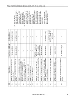
Page 27: ...m J Clearance to nonmechanical air supply inlet to building or the combustion air inlet to any other appliance 36 inches 91 cm 12 inches 30 cm K Clearance to a mechanical air supply inlet 6 feet 1 83 m 3 feet 91 cm above if within 10 feet 3 m horizontally L Clearance above paved sidewalk or paved driveway located on public property 7 feet 2 13 m 1 M Clearance under veranda porch deck or balcony 12...

Page 28: ...upersede these clearances Avoid termination locations near a dryer vent Avoid termination locations near commercial cooking exhaust 0 30 m to an inside corner 50 mm between Rinnai terminals at same level 0 91 m to ventilated or unventilated soffit or eve vent or to a deck or porch ...

Page 29: ...s in order to produce a stable water temperature and allow the water heaters to run efficiently Water heaters will turn on as necessary to meet the demand for hot water The EZConnect MSA 2MB and MSA 2S cannot be used on this model Refer to the instructions that come with the accessory for complete installation information WARNING DO NOT adjust the other dip switches unless specifically instructed ...

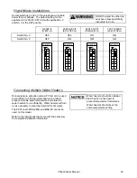
Page 30: ...be installed by itself and still operate the water heater All functions will be available with the exception that the clock function on the BC 100V will only be available if an MC 100V is also connected If 4 MC 91 s are installed simultaneously press the Priority and On Off buttons on the fourth controller until a beep sounds The table to the right shows some of the possible combinations of contro...

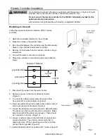
Page 31: ...y a registered installer WARNING Outline of Remote securing screw 1 21 32 3 5 16 securing screw wiring hole 7 Disconnect the power from the water heater 8 Remove a screw on the Quick Cable Connector Figure 1 9 To access the cable screws rotate the Quick Cable Connector 90º counterclockwise Figure 2 10 Insert wire cable through the Cable Access Hole so that it can be accessed from the back Figure 2...

Page 32: ...APPLIANCE 1 Turn off all electric power to the appliance using the ON OFF button 2 Set the thermostat to lowest setting 3 Locate the manual gas valve on the side of the heater Turn the manual valve clockwise to the full OFF position OPERATING INSTRUCTIONS 1 STOP Read the safety information above 2 Set the thermostat to lowest setting 3 Turn off all electric power to the appliance using the ON OFF ...

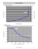
Page 33: ...1 2 3 4 5 6 0 10 20 30 40 50 60 70 80 90 100 0 0 1 0 2 0 3 0 4 0 5 0 6 0 0 25 50 75 100 125 150 Technical Data Pressure Drop Curve Outlet Flow Data V53e Pressure Loss psi Water Flow gpm delta T Temperature Rise ºF Pressure Loss ft head V53e Water Flow gpm ...

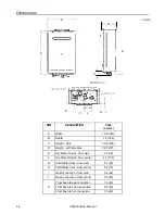
Page 34: ...Hot Water Outlet from wall 2 8 72 F Hot Water Outlet from center 4 1 105 G Cold Water Inlet from wall 2 1 53 H Cold Water Inlet from center 0 4 10 I Gas Connection from wall 2 4 62 J Gas Connection from center 3 3 83 From base to gas connection 1 6 40 From base to cold connection 2 0 50 From base to hot connection 1 6 42 K E F J H I G D B in mm K C A ...

Page 35: ... A B C SG SWITCHING POWERSUPPLY THERMISTOR CIRCUIT B SG RELAY 1 A WATERFLOW SENSOR CIRCUIT WATERFLOW CONTROLDEVICE CIRCUIT A SG A SG SG A QS SG FR FLAME DETECTING CIRCUIT FLAMEROD GND SG A REMOTE CONTROLLER CIRCUIT A B E PG A B C SG SG B VARISTOR ARRESTER GND SG WATERFLOW SENSOR WATERFLOW CONTROLDEVICE BY PASSFLOW CONTROLDEVICE M M DC12V DC170V D E PG SV3 SV2 SV1 SV0 RELAY DRIVING CIRCUIT D BY PAS...

Page 36: ...one _________________________________ _____________________________ Date of Purchase __________________________________ Model No ________________________________________ Serial No ________________________________________ Installed by ___________________________ Installer s License No _____________________ Address _____________________________ Phone _________________________________ Date of Install...

Page 37: ...hat is not covered This Warranty does not cover any failures or operating difficulties due to the following accident abuse or misuse alteration misapplication force majeure improper installation such as but not limited to inadequate water quality condensate damage improper venting incorrect gas type incorrect gas or water pressure or absence of a drain pan under the appliance improper maintenance ...

Page 38: ...38 V53e Outdoor Manual Notes ...

Page 39: ...V53e Outdoor Manual 39 Notes ...

Page 40: ...i Systems Domestic Hot Water Priority Optional Programmable Thermostat Zero Clearance to Combustibles Accommodates Standard Cased Coils Direct Vent Fireplace RHFE 750ETR Up to 83 AFUE Energy Efficiency Zero Clearance Installation Available in Four Options of Fronts Remotes and Fan Included Gas Conversion Kit Available Tankless Water Heaters Residential and Commercial Applications Continuous Hot Wa...

Reviews: