This appliance can be installed in ducted or recirculation
mode.
Ducted mode
(Fig. 4)
•
In ducted mode, the extractor hood fan extracts the
cooking vapours and passes them through the
grease filter. The air then flows to the outside.
•
The grease filter absorbs the solid particles in the
cooking vapors.
•
In this mode,
only grease filters are installed
(charcoal filter is optional)
.
Recirculation mode
(Fig. 5)
•
In recirculation mode, the extractor hood fan
extracts the cooking vapors which are purified in the
grease filter and charcoal filter.
•
The purified air is then recirculated into the kitchen
via a vent opening in the hood. The grease filter
absorbs the solid particles in the cooking vapors.
•
The charcoal filter is designed to absorb cooking
odor. In this mode,
both grease filters and charcoal
filters are installed.
Connection to exhaust air pipe
(Fig. 6 & 6.1)
•
Attach Ø150mm pipe directly to the air outlet and
secure appropriately (Fig. 6).
•
If using Ø120mm pipe, connect to the air outlet
using a reducing connector (not provided).
•
Secure both joints appropriately (Fig. 6.1).
•
Connect pipe to the outdoor duct.
•
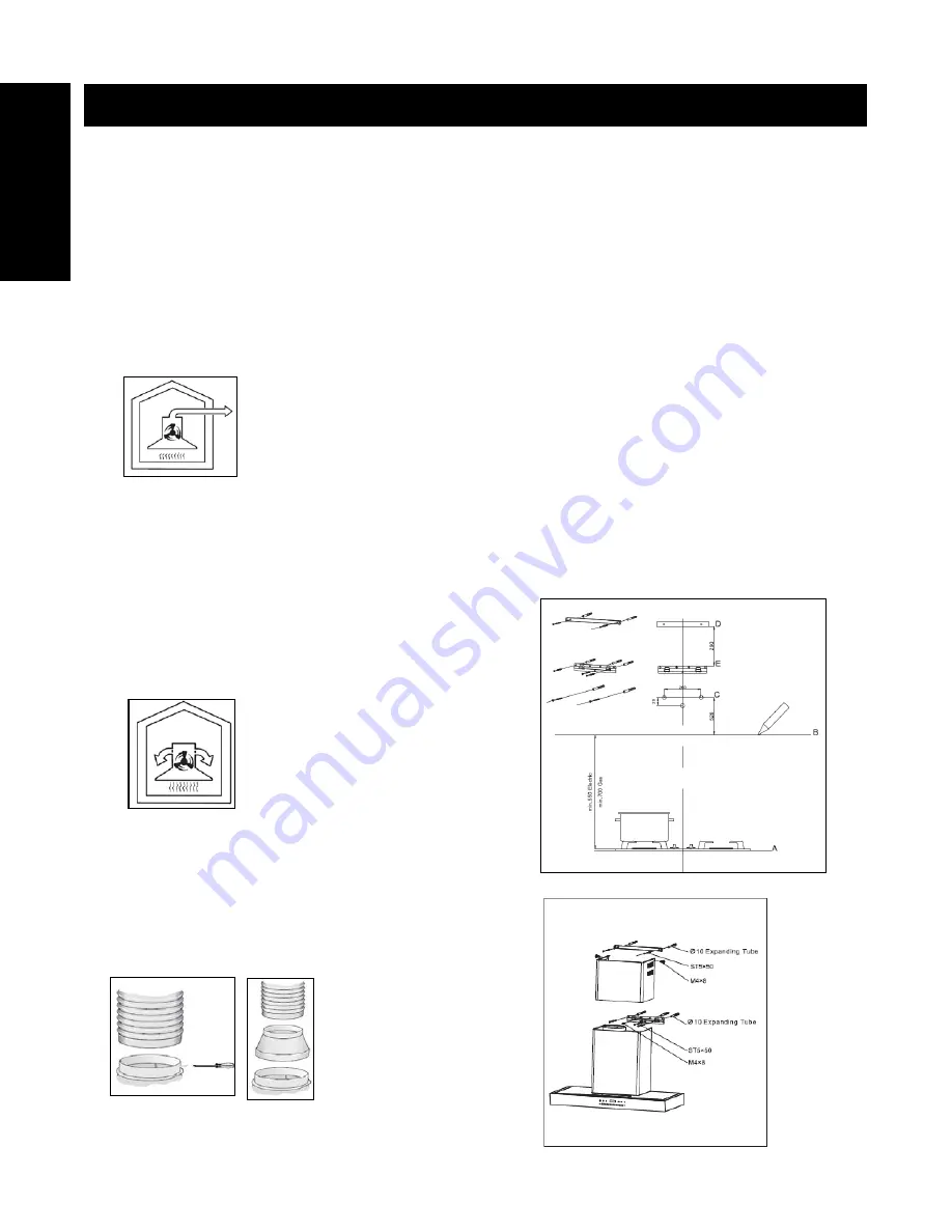
Wall mounting
(Fig. 7 & 8)
Do ensure that the appliance is mounted on a solid
surface which could withstand the appliance’s weight.
•
Draw a vertical line at the center of the wall.
•
From bench top (see A), draw a horizontal line above
minimum installation height level (see B).
•
Mark a reference point at C. Repeat this step on the
other side.
•
Drill Ø 8mm holes at center of marking points. Insert
wall plugs in the wall.
•
Fix the hood body to wall using 2 (two) ST5 x 50
screws provided. Tighten screws firmly. Note: Adjust
the hood body alignment if necessary (Fig. 9).
•
Place mounting bracket on the wall at desired height
level. Align bracket center at vertical line (see D).
•
Mark the center of the bracket holes and drill Ø 8mm
holes. Insert wall plugs in the wall.
•
Secure mounting bracket firmly using 2 (two) ST5 x
50 screws provided.
•
Fix the inner duct to both mounting bracket using 2
(two) M4 x 8 screws provided (Fig. 8).
•
Slide the outer duct downwards and ensure that it is
well seated on the hood body.
INSTALLATION
Fig. 4
En
glis
h
Fig. 5
Fig. 7
Fig. 6
Fig. 6.1
Fig. 8
4


