– 42 –
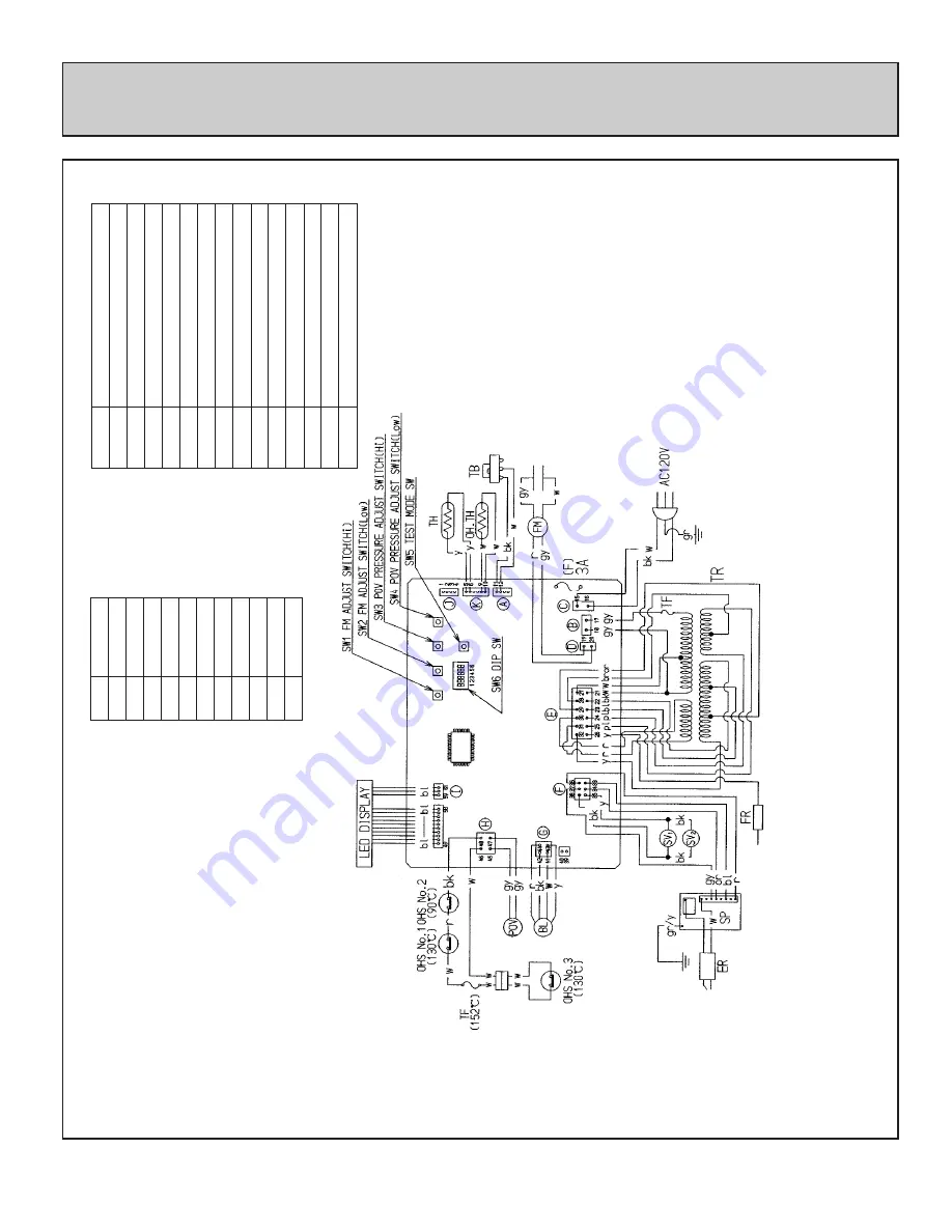
WIRING DIAGRAM
If any of the original wire as supplied with the appliance must be
replaced, it must be replaced with a wire of a least a 194
°F
temperature rating and number 18AWG or its equivalent.
“CAUTION: Label all wires prior to disconnection when servicing
controls. Wiring errors can cause improper and dangerous operation.
”
Verify operation after servicing.
CODE
COLOR
black
blue
brown
green
green/yellow
purple
bk
bl
br
gr
gr/y
pl
red
r
white
w
yellow
y
gray
gy
orange
or
MARK
TB
TH
TF
F
ER
POV
TR
FR
PART NAME
TERMINAL BLOCK
THERMISTOR
THERMAL FUSE
FUSE
ELECTRODE
MODULATING SOLENOID VALVE
TRANSFORMER
FLAME ROD
OH.TH
OVERHEAT THERMISTOR
OHS1~3
OVERHEAT SWITCH 1~3
FM
CONVECTION FAN MOTOR
SP
SPARKER
SV1~2
MAIN SOLENOID VALVE 1~2
BL
COMBUSTION FAN MOTOR
Summary of Contents for RHFE-431WTA
Page 13: ... 11 CUT AWAY DIAGRAM ...
Page 47: ... 45 SCHEMATIC DIAGRAM ...
Page 48: ... 46 ...
Page 49: ... 47 ...
Page 50: ... 48 ...
Page 51: ... 49 ...
Page 52: ... 50 PARTS LIST ...
Page 53: ... 51 ...
Page 54: ... 52 ...
Page 55: ... 53 ...
Page 63: ......


