


Reference Manual Rev 1.13
004R-646-113
Page 1
Table of Contents
1.
INTRODUCTION ...................................................................................................................... 6
1.1.
Overview ....................................................................................................................... 6
1.2.
The Manuals Set ........................................................................................................... 7
1.3.
Document Conventions ................................................................................................. 7
1.4.
Software Comparison K404, K405 and K422 ............................................................... 7
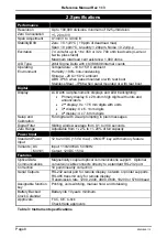
2.
SPECIFICATIONS .................................................................................................................... 8
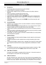
3.
INSTALLATION ....................................................................................................................... 9
3.1.
Introduction ................................................................................................................... 9
3.2.
General Warnings ......................................................................................................... 9
3.3.
Electrical Safety ............................................................................................................ 9
3.4.
Cleaning ........................................................................................................................ 9
3.5.
Panel Mount Template .................................................................................................. 9
3.6.
Cable Connections ........................................................................................................ 9
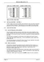
3.7.
DC Power (DC PWR + , DC PWR –) .......................................................................... 10
3.8.
Load Cell Connection .................................................................................................. 10
3.8.1.
Load Cell Signals and Scale Build .............................................................. 10
3.8.2.
4-Wire Connection ...................................................................................... 10
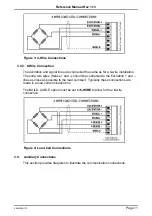
3.8.3.
6-Wire Connection ...................................................................................... 11
3.9.
Auxiliary Connections .................................................................................................. 11
3.9.1.
RS-232 Serial .............................................................................................. 12
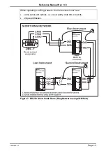
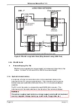
3.9.2.
RS-485 Serial .............................................................................................. 14
3.10.
Optical Communications ............................................................................................. 14
3.11.
Connecting Shields ..................................................................................................... 15
3.11.1.
Cable Shield Connection and Earthing ....................................................... 16
3.12.
Regulatory Sealing Requirements .............................................................................. 16
3.13.
Accessory Module connection .................................................................................... 17
4.
SETUP MENUS ...................................................................................................................... 18
4.1.
Accessing Setup Menus .............................................................................................. 18
4.1.1.
Setup Display Prompts ............................................................................... 19
4.2.
Exiting Full or Safe Setup ............................................................................................ 19
4.3.
Menu Navigation ......................................................................................................... 19
4.4.
Changing Data ............................................................................................................ 20
4.5.
Numeric Entry ............................................................................................................. 20
4.6.
Selections and Options ............................................................................................... 21
4.7.
Strings ......................................................................................................................... 21
4.7.1.
Normal String Editing .................................................................................. 21
4.7.2.
Numerical String Editing ............................................................................. 22
4.7.3.
ASCII String Editing .................................................................................... 22
4.8.
IP Addresses ............................................................................................................... 22
5.
BASIC OPERATION .............................................................................................................. 23
5.1.
User Interface Display and Controls ........................................................................... 23
5.1.1.
Overview ..................................................................................................... 23
5.1.2.
Display ........................................................................................................ 24
5.1.3.
Primary Annunciators .................................................................................. 24
5.1.4.
Keypad ........................................................................................................ 25
5.2.
Operation Keys ........................................................................................................... 26
5.2.1.
Turn Instrument ON - Short press <Power> ............................................... 26
5.2.2.
Turn Instrument OFF - Long press <Power> .............................................. 26
5.2.3.
Additional Power Information ...................................................................... 26
5.3.
Zero Key ...................................................................................................................... 26
5.4.
Tare Key ...................................................................................................................... 27
5.4.1.
Setting Preset Tare on a Permanent Truck ID ............................................ 27
5.4.2.
Setting Preset Tare on a Temporary Truck ID ............................................ 27
5.4.3.
Gross/Net Key ............................................................................................. 28
5.5.
Truck Key .................................................................................................................... 28
5.5.1.
Truck Key to enter an ID ............................................................................. 28
5.5.2.
Truck Key to select a Truck ID .................................................................... 28


