


Summary of Contents for X300 IP69K376
Page 1: ...X300 IP69K K376 K378 Digital Indicator Reference Manual...
Page 3: ...Notes...
Page 75: ...Notes...
Page 76: ......
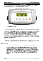
The Rinstrum X300 IP69K376 is a rugged and reliable weighing indicator designed for harsh industrial environments. For detailed instructions on how to use this product, be sure to download the Reference Manual for free from our website. Get your manual now at 88.208.23.73:8080.
Page 1: ...X300 IP69K K376 K378 Digital Indicator Reference Manual...
Page 3: ...Notes...
Page 75: ...Notes...
Page 76: ......


