


Reference Manual V1.16
Software Versions 4.xx
003X-652-116
Page 9
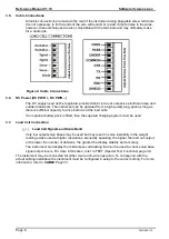
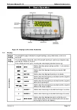
4-Wire Connection
The minimum connectivity requirements are the connection of four wires (i.e. Exci and
– along with and –). Internally the
instrument
has a precision analogue switch that
connects the Sense + and
– lines directly to the Exci and – lines when 4-wire mode is
selected.
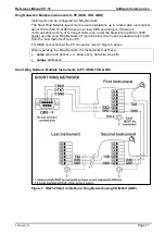
A 4-wire connection is only suitable for short cable runs. Where long cable lengths are
needed, a 6-wire extension is required to maintain accuracy.
The BUILD:CABLE option must be set to
4
to allow for 4-wire connection. Refer to
page 33.
Figure 3: 4-Wire Connections
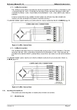
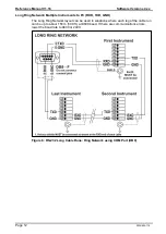
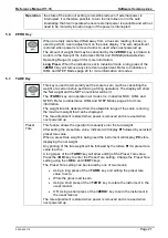
6-Wire Connection
The excitation and signal lines are connected the same as for a 4-wire installation. The extra
two wires (Sense + and
–) should be connected to the Exci and – lines as close as
possible to the load cell itself. Typically these connections are made in a load cell termination
box.
The BUILD:CABLE option must be set to
6
(the default) to allow for 6-wire connection. Refer to
page 33.
+++
Figure 4: 6-Wire Connections
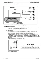
3.8.
Auxiliary Connections
This section provides diagrams to illustrate the terminal connections.
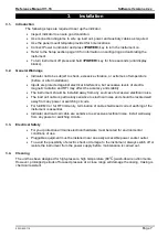
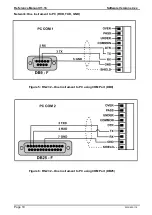
RS-232 Serial
Summary of Contents for X300 IP69K376
Page 1: ...X300 IP69K K376 K378 Digital Indicator Reference Manual...
Page 3: ...Notes...
Page 75: ...Notes...
Page 76: ......


