background image

136

Settings and Other Information

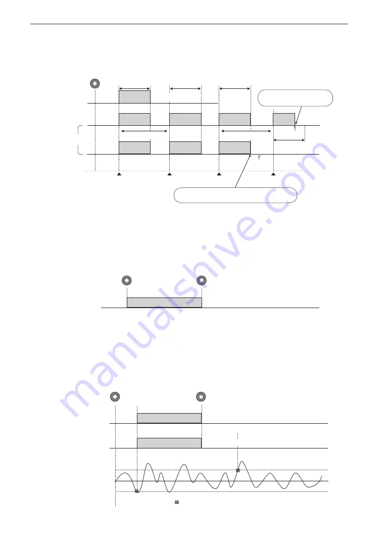
Data recording: Recording time (1 s to 24 h), Time trigger (6), (7)

Data recording: Manual (controlled with [STOP] key), no trigger (8)

REC

Interval

Recording completed

[Start time]

Time trigger

Time trigger

Time trigger

Time trigger

Interval

Trigger

standby

Trigger

standby

Trigger

standby

Recording

in progress

Recording

in progress

Recording

in progress

Recording

in progress

Recording

in progress

Recording

in progress

Recording

in progress

. . .

. . .

Trigger

standby

Trigger

standby

Recording

in progress

If next time trigger would be later than stop time setting, 
recording ends at this point

Recording ends when stop time 
is reached during recording

Recording 
completed

Recording 
completed

[Stop time]

[Stop time]

(7) Repeat

Recording time

(1 s to 24 h)

(6) Single

Recording time

(1 s to 24 h)

Recording time

(1 s to 24 h)

Recording time

(1 s to 24 h)

Data recording: Manual (controlled with [STOP] key), 
Level trigger (9), (10)

(8) Free

Recording completed

REC

STOP

Recording in progress

(10) Repeat

(9) Single

Trigger

standby

Trigger

standby

Trigger channel

waveform

Level trigger event

Trigger level

Trigger level

Recording completed

Recording completed

REC

STOP

Recording in progress

Recording in progress

Summary of Contents for DA-21

Page 1: ...3 20 41 Higashimotomachi Kokubunji Tokyo 185 8533 Japan http www rion co jp english INSTRUCTION MANUAL 4 channel Data Recorder DA 21...

Page 2: ......

Page 3: ...ontrols and Functions Explains the keys indicators connectors and all other parts on the panels of the unit Power On Off Explains how to turn the unit on and off Display Explanation Explains the vario...

Page 4: ...unit for recording data Specifications Lists the technical specifications of the unit Company names and product names mentioned in this manual are usually trademarks or registered trademarks of their...

Page 5: ...sure that all instructions are fully understood and observed Caution Important Disregarding instructions printed here incurs the risk of injury to persons and or dam age to peripheral equipment Disreg...

Page 6: ...music CD Inserting this disc in a CD player poses the risk of excessive volume levels that can cause hearing damage and damage to the CD player Be careful around rotating machinery When using the uni...

Page 7: ...e CD ROM drive Otherwise there is a risk of damage to the CD ROM drive Handle batteries correctly If batteries are inserted with wrong polarity or otherwise mishandled battery fluid may leak and overh...

Page 8: ...ther chemicals Do not use or store the unit in slanted or instable locations Do not use or store the unit in locations that may be subject to vibra tions or shock If batteries are inserted with wrong...

Page 9: ...s a pencil screwdriver etc Take care that no conductive objects such as wire metal scraps conductive plastics etc can get into the unit Do not disassemble the unit or attempt internal alterations In c...

Page 10: ...ion Support Room http svmeas rion co jp Note that we assume no responsibility for the source code Note that we are not responsible for exact details of the source code For details on the license click...

Page 11: ...39 Input menu 39 Rec Parameters menu 44 Trigger menu 46 Bar Graph menu 50 System menu 51 Synchronization menu 55 Preparations 56 Preparations and checks before recording 57 Power supply 57 SD memory...

Page 12: ...02 Data recording example 105 Recall Playback of Recorded Data 108 Activating recall mode 108 Playback of recorded data 111 Canceling recall mode 115 Other information 115 Messages 119 Filter Characte...

Page 13: ...alkaline batteries will power the unit for about 8 hours of continuous use at 23 C frequency range setting 100 Hz 4 channel input CCLD off backlight off CCLD support allows easy hookup of sensors inc...

Page 14: ...or similar equipment Supplied viewer software AS 70 Viewer for use on a computer provides the required features for checking and storing the recorded waveform data including voice memo and marker as...

Page 15: ...est sound and vibration data Road traffic noise sound pressure waveform data Product inspection data Other data Playback signal monitoring output Temperature meter Microphone Accelerometer Sound level...

Page 16: ...main screen brings upamenuscreen Thereareanumberofmenuscreens thatgiveaccesstorecordingparameters inputsettings and various other settings see page 30 Recording procedure Pressing the REC key at the...

Page 17: ...OVERLOAD CARD CAPACITY LIGHT RECALL RANGE CLEAR Ov MENU 4 3 2 1 1 POWERkey 2 STOPkey 3 PLAYkey 4 RECkey 5 PAUSEkey 13 MENUkey 12 RANGEkey 11 RECALLkey 9 LIGHTkey 10 CLEAROvkey 7 ENTkey PAUSE indicator...

Page 18: ...layback The key is also used for menu operations and other functions 3 PLAY key Serves to start data playback 4 REC key Serves to start data recording 5 PAUSE key Serves to pause and resume data playb...

Page 19: ...see page 24 11 RECALL key Serves to activate the recall mode and to cancel the recall mode and return to the main screen 12 RANGE key Serves to activate and cancel the input range setting condition In...

Page 20: ...the indicator is lit 2 PLAY indicator Indicates that recorded data are being played back Flashing in green Recorded data are being played back 3 REC indicator Indicates the operating condition during...

Page 21: ...ta recording will stop within 10 minutes Also while the indicator is not flashing the currently available recording time is shown on the display in the format XXX XX XX Before starting to record you s...

Page 22: ...battery adapter CC 82 can be connected here Important Do not connect any AC adapter or car battery adapter except for the specified models Oth erwise the unit may be damaged The optional car battery a...

Page 23: ...l for recording 6 Output connectors While recorded data are being played back in recall mode the playback signal is available at these connectors 7 Monitor Out connector The input signal or playback s...

Page 24: ...rd allows storing data and exporting data to a computer The card slot is also used for upgrading the system firmware etc Note Use only RION supplied SD memory cards certified for operation in the DA 2...

Page 25: ...ake care not to reverse the and polarity when inserting the batteries see page 57 When using the wake up on power mode there should be no batteries inserted in the unit Remove the batteries from the u...

Page 26: ...s not appear straight away Instead a message screen is shown asking whether you want to load the settings from the card or use the settings that were established before power was last turned off POWER...

Page 27: ...ning the power off When you keep the POWER key depressed the shutdown screen as shown below appears on the display and the unit is turned off Note that if a icon is shown at the bottom of the display...

Page 28: ...ckly re establish these settings at power on This reduces the time required for startup and the risk of making setup errors To create a setting file use the Read Save Settings item on System menu see...

Page 29: ...7 Display Explanation Display screen Recording operation mode indication page 20 Recording parameter indication page 18 Trigger setting indication page 21 Status indication page 22 Channel data page 2...

Page 30: ...d sampling frequency is as shown in the table below Frequency range Sampling frequency 2 56 2 4 100 Hz 256 Hz 240 Hz 500 Hz 1 28 kHz 1 2 kHz 1 kHz 2 56kHz 2 4 kHz 5 kHz 12 8 kHz 12 kHz 10 kHz 25 6 kHz...

Page 31: ...he STOP key is pressed or the SD memory card runs out of space recording stops In this case the actual recorded data time will be shorter than the recording time setting The recording time also includ...

Page 32: ...Recording in progress flashing Trigger standby permanently on Playback paused flashing Rewind recall mode only flashing Fast forward recall mode only flashing 2 All channel overload indication This i...

Page 33: ...r Repeat Level Repeat level trigger Single Time Single time trigger Repeat Time Repeat time trigger Single Ext Single external trigger Repeat Ext Repeat external trigger Single Ext Gate Single externa...

Page 34: ...time 1 Card icon remaining capacity The remaining card capacity is shown here in data size and the remain ing recording time as calculated from the currently selected sampling frequency and number of...

Page 35: ...tion where the operation keys except for LIGHT and are disabled For details on the key lock function see page 86 The condition is activated by pressing and holding the and keys together for a few seco...

Page 36: ...r overload information 3 Bar graph 1 Level trigger target channel When the level trigger function is used the indication TRG is shown to the left of the channel indication 2 Channel number overload in...

Page 37: ...has been selected in the Bar Graph menu see page 50 If the sensor type for the channel has been set to SLM VM in the INPUT menu see page 39 this mode cannot be selected Logarithmic value display bar...

Page 38: ...le value Depending on the Sens and Sensitivity settings in the Input menu the value corresponding to the bar graph full range point is shown here A list of the menu settings and values units is shown...

Page 39: ...he channel number CH5 is shown here If an overload signal is input the channel number switches to the overload information see page 24 2 Bar graph and setting information Depending on the setting made...

Page 40: ...the invalid indication is shown Underload signal evaluation Under is shown when revolution speed is 200 rpm or lower Under the lower limit of 190 rpm the invalid indication is shown Voice Memo setting...

Page 41: ...me up to 20 seconds before and the vertical axis is the level Also during history display you can switch the monitor channel with the keys 1 Channel information From left the display shows the voice m...

Page 42: ...age When a menu has been selected the screen with the individual settings of that menu appears There are a total of six menu pages divided by category such as input related settings recording settings...

Page 43: ...4 Select an item Use the keys to move the cursor to the desired setting item ENT ENT 5 Initiate the change Press the ENT key to start changing the selected item There are three ways of changing a sett...

Page 44: ...High pass filter Low pass filter Sensor type Rec Parameters Frequency Range Sampling Frequency etc Trigger Trigger Mode Trigger Type etc Bar Graph Bar Graph Display Type System Play Signal Output Bac...

Page 45: ...disappears ENT Confirm change LPF OFF setting has changed to 200 Hz A 2 By pressing the MENU key or STOP key instead of the ENT key you can cancel the sub menu without changing the setting In this ca...

Page 46: ...ensitivity Rec Parameters Recording time Pre recording time Trigger Trigger level Recording start time Recording stop time System Device index number clock setting The explanation below uses the CH2 S...

Page 47: ...s ENT Confirm change Sensitivity set ting has changed to 130 dB from 100 dB B 2 By pressing the MENU key or STOP key instead of the ENT key you can cancel the sub menu without changing the setting In...

Page 48: ...Format and Read Save Settings on the System menu To execute the process press the key corresponding to Yes To cancel the process press the key corresponding to No When the process is completed the ori...

Page 49: ...nging an item on another menu page Press the MENU key to bring up the menu list 8 Return to main screen Press the MENU key or STOP key to return to the main screen MENU To change an item on another me...

Page 50: ...to go to a menu page ENT MENU MENU STOP MENU ENT STOP ENT STOP ENT ENT MENU PAUSE M a i n s c r e e n Menu list M e n u s c r e e n Menu pages Only one menu page can be used at a time To go to anothe...

Page 51: ...This is suitable for en vironment sensors temperature wind speed pressure etc and sound level meters that output the measurement value as a DC signal The setting should also be used when recording a s...

Page 52: ...elect this setting when the accelerometer is connected to the unit via the charge converter VP 40 etc see page 63 Inp Tachometer signal voice memo marker setting CH5 This setting determines which sign...

Page 53: ...is available for the high pass filter OFF 5 Hz LPF Low pass filter frequency setting Enables a low pass filter for the input signal The LPF frequency indicates the cutoff frequency Available settings...

Page 54: ...ding SLM Sound level meter with AC or DC output is con nected VM Vibration level meter with AC or DC output is connected CCLD V Constant Current Line Drive compatible sensor is connected Record input...

Page 55: ...U Voltage per EU V EU Note that the EU setting value is the inverse of that used in the DA 20 MIC Constant Current Line Drive compatible microphone sensitivity level dB PICK CCLD Voltage sensitivity o...

Page 56: ...sampling frequency settings com monly used for frequency analyzers and voice processing 2 4 times or 2 56 times the frequency range FFT analyzers generally use 2 56 times 2 4 2 56 Bit Length Bit leng...

Page 57: ...cording stops automatically However if the STOP key is pressed before that or if the SD memory card becomes full recording stops at that point 1 s to 59 s seconds 1 m to 59 m minutes 1 h to 24 h hours...

Page 58: ...y is pressed When a trigger event occurs recording starts When the amount of data corresponding to the recording time has been recorded recording stops Repeat The unit goes into trigger standby mode w...

Page 59: ...ost recording Time Recording is carried out from the specified Start Time to the specified Stop Time at intervals as specified by the Interval setting Level Trigger level setting When the trigger sign...

Page 60: ...auto matically becomes current time 5 minutes When the stop time setting is before the current time the setting automatically becomes Start Time 24 hours Interval Recording interval setting When the t...

Page 61: ...t wakes up and goes into standby until the actual start Pressing the LIGHT key in the power save state temporarily turns on the LCD screen If no further key is pressed the unit will return to the powe...

Page 62: ...hod Lets you select linear value display Linear or logarithmic value display Log for each channel For details on the bar graph display method see page 27 Linear Log Note The Graph menu will be blank f...

Page 63: ...d data deleting Read Save Setting Read setting values from unit or SD memory card Save setting values in unit or on SD memory card Load Default Settings Returns all unit settings to the initial factor...

Page 64: ...etting file saved on the SD memory card can also be used as startup file for loading when the unit is turned on see page 14 If the message Card Error appears when you press the ENT key to update the s...

Page 65: ...Continue To have the backlight continuously on select Continue Battery Type Used battery type setting Displays the sub menu to select the type of battery used for the unit The remaining battery capac...

Page 66: ...g on page 111 Index Device index number setting Using this setting you can assign a unique number to each DA 21 device The setting range is 1 to 255 Because the index number information is recorded al...

Page 67: ...his setting on the DA 21 to be used as slave Synchronize Synchronize connected DA 21 units Use the dedicated cable to connect the two DA 21 units to be used as master and slave Select this item on bot...

Page 68: ...rations insertion and removal formatting 3 Connection of external devices sensors etc 4 Sensitivity setting Recording parameter settings 1 Input range overload 2 Frequency range sampling frequency 3 R...

Page 69: ...nt 3 Replace the battery compartment cover Important Take care not to reverse the and polarity when inserting the batteries Always replace all four batteries together Do not mix old and new batteries...

Page 70: ...an AC outlet To remove the AC adapter turn the DA 21 off and then perform the above steps in reverse order Important Use only the specified AC adapter available as an option for the DA 21 Using anothe...

Page 71: ...kup battery is achieved after 24 hours Charging time Retention period 1 hour 2 days 12 hours 30 days 24 hours 45 days Use the AC adapter when connecting external power for battery charge while the uni...

Page 72: ...ch a case the POWER key on the panel has no effect Important When setting the WAKE UP ON POWER switch to ON remove all batteries from the battery compartment Otherwise the wake up on power mode will n...

Page 73: ...enu is set to ON without having to install a USB driver For connection to the DA 21 and the computer use an optional generic A mini B USB cable Important SD memory cards even from the same manu factur...

Page 74: ...ty for any damage or loss of stored measurement data 1 Open the card slot cover of the unit 2 Insert the SD memory card into the card slot with the label of the card facing up Push the card in until i...

Page 75: ...the card is formatted by this unit In the following cases you should format the SD memory card When using the SD memory card in the unit for the first time When wishing to delete all data from the SD...

Page 76: ...Tri axial accelerometer cable VP 51WL Charge converter To input connectors BNC BNC cable Preamplifier NH 22 Microphone UC 59 UC 52 To ACOUT BNC BNC cable VP 40 90001 RION VP 40 90001 RION VP 40 90001...

Page 77: ...ut DC com ponents DC components and components 0 3 Hz or below are blocked Example AC output of sound level meter or vibration meter DC For sensors that output an electrical signal including DC Exampl...

Page 78: ...sensor signal units are determined au tomatically as shown in the table below Indication for Sensor item in menu Unit as shown on main screen Scaled unit set for Sensitivity item in menu Value input...

Page 79: ...V Pa or level range full scale value of sound level meter or vibration level meter Microphone Example For UC 53A rated for 28 dB and used together with NH 22 the transmission loss is taken as 0 8 dB a...

Page 80: ...practical examples for applying the respective formula to actual sensitivity values are shown below These values are shown as input range When the exponent is two digits the mantissa is shown as one...

Page 81: ...ophone UC 52 Preamplifier NH 22 CCLD MIC Sensitivity level 0 1 to 99 9 dB 0 dB 1 V Pa Piezoelectric accelerometer with built in amplifier PV 90I CCLD PICK Voltage sensitivity 0 01 to 99 9 mV m s2 Piez...

Page 82: ...ting the input range as low as possible without causing overload is generally preferred For inspection of products and oth er kinds of periodic measurements it may be necessary to keep the input range...

Page 83: ...setting Use the keys to change the input range 5 Confirm the new input range setting Press the ENT key to return to the condition of step 2 6 If you want to change the input range for another channel...

Page 84: ...enient This indication comes on when there has been an overload event at any time within a given period To reset the indication hold down the CLEAR Ov key When the key is released overload history mon...

Page 85: ...enu The frequency range value represents the highest effective frequency that will be included in the recorded waveform Higher components will be cut off When making the setting choose a value that is...

Page 86: ...l also stop when the SD memory card becomes full Data recorded up to that point will be stored Setting the recording time The recording time can be set to 1 s to 59 s seconds 1 m to 59 m minutes 1 h t...

Page 87: ...value of 2 seconds or higher When the Pre Recording Time has been set to 5 seconds the recording time can be set to a value of 6 seconds or higher The recording time setting cannot exceed the remaini...

Page 88: ...e 45 Difference in recording procedure with Pre Recording Time Pre Recording Time 5 s Recording Time other than Manual Trigger Mode Free PreRec Time 0 s PreRec Time 5 s REC Recording procedure Data re...

Page 89: ...the Free setting Free trigger off Recording starts immediately when the REC key is pressed and ends when the amount of data corresponding to the recording time has been recorded Single single trigger...

Page 90: ...gger Type Level or External Free Single Repeat Trigger events During data recording trigger event is disregarded REC Trigger standby Data recording in progress Recording procedure Recording procedure...

Page 91: ...ted later than the time which ful filled trigger conditions If you want to record all the waveforms which fulfilled trigger conditions set the Pre Recording Time in Rec Parameters menu as 1 second or...

Page 92: ...ording in progress Data recording in progress Data recording in progress Data recording in progress Trigger standby Trigger standby Trigger standby Data recording in progress Data recording in progres...

Page 93: ...el the channel to be used as trigger channel must be set Make the setting using the Ch item in Trigger menu The indication TRG is shown at the left of the trigger channel For information on level trig...

Page 94: ...er menu When Stop Time is reached before Recording Time is up Stop Time Start Time Interval Recording Time 1 s to 24 h Recording Time 1 s to 24 h Data recording in progress Data recording in progress...

Page 95: ...itten Data recording in progress Data recording in progress File is being written File write time Recorded data are also written sequentially to a file during the recording process but at the point wh...

Page 96: ...x number can serve to manage data according to the unit on which the data were recorded Example 2 Manage recorded data according to measurement purpose measurement location or similar Example 3 Manage...

Page 97: ...Voice Input connector can be recorded When the Inp item for CH5 in the Input menu is set to Voice Memo the indication appears to the right of the bar graph The level of the voice signal is shown by t...

Page 98: ...rker Voice memo Voice memo Voice memo Voice memo Recording start Microphone switch status Voice memo before recording Voice memo or marker according to setting after recording start Released Pressed I...

Page 99: ...keys inactive Pressing and holding the and keys together for a few seconds activates the key lock condition In this condition all keys except the LIGHT key and the keys are locked Remote control oper...

Page 100: ...data in recall mode cannot be deleted Only the input range setting can still be changed This condition is called the menu lock mode When menu lock is active the indication MENU LOCKED appears if you...

Page 101: ...ertent operation Remote Controller connector Remote Controller Operation status indicator Ext Trig Remote Controller START STOP switch DC IN 5 20V USB Sync Voice Input Monitor Out Tacho Output Input 1...

Page 102: ...ctor of the DA 21 with a USB connector of a computer using the optional generic A mini B USB cable as shown below DC IN 5 20V USB Sync Voice Input Ext Trig Monitor Out Remote Controller Tacho Output I...

Page 103: ...Check the synchronization information on the display page 18 after operation of the syn chronization Note The size of data files recorded simultaneously on two synchronized DA 21 units will be differe...

Page 104: ...use as slave unit 4 Enable synchronized operation by selecting Synchronize in the Synchronization menu on both units 5 The execution choice screen appears Press the ENT key on both units simultaneous...

Page 105: ...on speed is displayed Connection example Connecting a rotary pulse generator The BNC BNC coaxial cable EC 90 series option can be used to connect a rotary pulse generator equipped with a BNC output as...

Page 106: ...nsidered to provide sufficient accuracy recording a calibration signal is not necessary 3 Recording Use the REC key to perform the recording procedure and repeat as necessary If any of the items that...

Page 107: ...required and then check remaining recording time on main screen See pages 9 22 129 4 External equipment connection Is sensor configuration appropriate Have sensor been connected correctly See pages 1...

Page 108: ...setting you want to change 3 Press the ENT key to allow changing the current input range setting 4 Use the keys to change the input range 5 Press the ENT key 6 If you want to change the input range f...

Page 109: ...been changed Input range information of measuring device will also be required if range switching is possible In the representative examples listed below recording the calibration signal may be necess...

Page 110: ...not start from zero but from the Pre Recording Time value REC If one of the following messages appears and recording does not start NoCard Insert an SD memory card and press any key to clear the messa...

Page 111: ...being recorded i e where the unit is not in the trigger standby condition is called recording in progress Overload history and display The overload history display OVER can be turned off during recor...

Page 112: ...s After a long term recording or when there is a large number of files on the SD memory card data recording to the SD memory card may take some time Do not remove the SD memory card during data record...

Page 113: ...various conditions with and without the use of the trigger function Flashing of an indicator or icon is indicated in the illustration as REC indicator REC icon REC Recording procedure Recording in pr...

Page 114: ...cording procedure voice memo recording is possible at any time When voice memo recording was stopped but the voice memo file is still being written to the SD memory card the REC key is not accessible...

Page 115: ...not in progress and voice memo recording is possible at any time regardless of voice memo marker setting However while a voice memo file is being written to the SD memory card REC S1 is not accepted...

Page 116: ...e switch is kept depressed The same applies for recording end when the trigger function is not used Voice Memo Marker Microphone switch status Released Pressed S1 S2 REC REC Voice memo Voice memo Reco...

Page 117: ...the optional voice memo microphone to the Voice Input connector Input the AC signal of the sound level meter to the channel 1 CH1 connector of the DA 21 Make the DA 21 settings as follows Input settin...

Page 118: ...should be set to Free 2 Cancel calibration mode at sound level meter Set trigger mode back to Repeat and recording time to 15 s 3 Press the REC key to enable trigger standby 4 Record voice memo as nec...

Page 119: ...tor To I O connector Comparator output cable CC 42C To Input 1 connector To Ext Trig connector To Voice Input connector BNC mini plug cable CC 24S CC 24 can also be used Voice memo microphone 4 3 2 1...

Page 120: ...pears and the unit switches to recall mode Note When there are a lot of data on the SD memory card entering recall mode may take some time The Select File screen can show up to latest 1 000 files Main...

Page 121: ...meter signal For data recorded with the repeat trigger function the number of the trigger event is shown on the Status field For example Trigger 1 indicates data recorded at the first trigger event Us...

Page 122: ...rmation about recording time input range overload history etc The recording time is the time corresponding to the actual recorded data For data where recording was stopped partway this will be shorter...

Page 123: ...he display When all recorded data have been played playback stops During playback the bar graphs are linked to the playback signal The recording time indication changes to elapsed playback time indica...

Page 124: ...layback icon go out and the unit returns to the recall screen Pausing and restarting playback Press the PAUSE key Playback is halted temporarily In this condition the pause icon flashes on the display...

Page 125: ...al is output If the playback position was moved all the way to the end of the recorded data playback will stop when you release the key If the playback position was moved all the way to the beginning...

Page 126: ...orward or reverse is about 60 times higher than regular playback If you press the or key and release it within less than one second the unit jumps to the voice memo start position or marker position E...

Page 127: ...tput from a channel for which CCLD is selected The power supply condition is checked and the unit may be shut down if battery capacity is insufficient In such a case replace the batteries with a fresh...

Page 128: ...ect File screen in recall mode Important Do not change the wav file name The file data is not played back correctly DA21 INI Record YYYY MM DD_HHMMSS WR_xxx_YYYYMMDD_HHMMSS_yyyy wav MM_xxx_YYYYMMDD_HH...

Page 129: ...see page 52 You can also store the file with a suitable file name on the computer and use different files to manage various settings Important Use only RION supplied SD memory cards Operation with oth...

Page 130: ...m o d e Change file number Delete selected recorded data Recall screen Change file number End is reached during playback or Playback screen Playback in progress During playback pause Fast forward reve...

Page 131: ...Record Card Voice memo recording Number of data Voice memo recording MENU LOCKED Menu display data deletion NoCard Recording start Recall mode Disconnect the USB Recording start Recall mode Now Closin...

Page 132: ...ines If these cannot be completed within a certain period this message appears Countermeasure Press the ENT key to clear the message and then perform a power down power on cycle Condition Indication A...

Page 133: ...AT32 or the card is defective Countermeasure Press the ENT key to clear the message Format the card in the DA 21 If the message is still shown try a different SD memory card Formatting a card will per...

Page 134: ...o activate recording by pressing REC Description There is not enough space on the SD memory card to write data Countermeasure Press the ENT key to clear the message Data recorded up to that point will...

Page 135: ...t the SD memory card Alternatively provide another SD memory card Condition Attempted to start recording procedure Attempted to record voice memo from main screen Description One of the following acti...

Page 136: ...rt an SD memory card Condition Attempted to start recording procedure Tried to enter recall mode Description USB Storage in the System menu is selected ON Countermeasure Press the ENT key to clear the...

Page 137: ...iously recorded data will also be destroyed While the message is being shown the REC key is inactive and any trigger event is disregarded Condition Data recording is completed Voice memo recording fro...

Page 138: ...lt condition Countermeasure Press the ENT key to clear the message Make the required settings again before starting to record Description This message asks for check after operation of inter unit sync...

Page 139: ...like to inter rupt operation Condition When pressing the MENU key of synchronized DA 21 Description This message asks for re synchronization of the DA 21 units because the synchronization of DA 21 uni...

Page 140: ...pass filter is set to the cutoff frequency of the frequency range The available high pass filter settings are OFF and 5 Hz For DC channels the available setting is OFF For AC and CCLD channels a 0 3 H...

Page 141: ...ed automatically The available recording time differs depending on the type of SD memory card Please note that these are approximate values provided for reference 2 GB SD memory card Sampling frequenc...

Page 142: ...CH4 Sensor signal type OFF DC AC CCLD VP4x Inp CH5 CH5 input signal type OFF Tacho Voice Memo Marker HPF High pass filter frequency OFF 5 Hz LPF Low pass filter frequency OFF 200 Hz 1 kHz 2 kHz Sens...

Page 143: ...interval 2 5 m 10 m 15 m 30 m 1 h 8 h 24 h Sleep Sleep mode OFF ON 1 Trigger level and trigger channel to be set when trigger signal type is Level 2 Start time stop time and recording interval to be s...

Page 144: ...ng Date year month day 2013 01 01 to 2037 12 31 Time hour minute second 00 00 00 to 23 59 59 Backlight Settings Screen backlight setting Brightness Backlight brightness 1 to 4 Auto Off Backlight auto...

Page 145: ...e Parameter 1 Recording Time 1 s to 24 h Free 2 Level Single Level Trigger level Ch Trigger channel 3 Repeat 4 External Single 5 Repeat 6 Time Single Start Time Stop Time Sleep 7 Repeat Interval Recor...

Page 146: ...revious table Pre recording Pre Recording Time Post recording Recording stop due to STOP key operation or insufficient SD memory card capacity Mode Free 1 8 Level 2 3 9 10 External 4 5 11 12 Time 6 7...

Page 147: ...aveform Level trigger event Trigger level Trigger level Trigger standby REC Recording in progress Recording in progress Recording in progress Recording time 1 s to 24 h Recording time 1 s to 24 h Data...

Page 148: ...ecording in progress If next time trigger would be later than stop time setting recording ends at this point Recording ends when stop time is reached during recording Recording completed Recording com...

Page 149: ...4 Repeat STOP Single Repeat Recording in progress Trigger standby Trigger standby Recording in progress Recording in progress Recording completed Recording completed Start time Stop time Recording com...

Page 150: ...s2 0 015 m s2 PV 97I X 0 069 m s2 0 023 m s2 Y 0 065 m s2 0 021 m s2 Z 0 080 m s2 0 022 m s2 PV 97C VP 40 X 0 224 m s2 0 102 m s2 Y 0 215 m s2 0 095 m s2 Z 0 191 m s2 0 114 m s2 NH 22 UC 59 A 23 3 dB...

Page 151: ...file is made up of variable length blocks called chunks The basic structure is as follows The chunks and file structure used by the DA 21 are shown below RIFF Wave Chunk Chunk 1 chunkID xxxx chunkSiz...

Page 152: ...sub chunk Type sub chunk 40960 bytes 24 bytes 652 bytes Common chunk 40960 bytes Wave Settings chunk Padding chunk 36 bytes 196 bytes 456 bytes 114 bytes 4 channels 268 bytes CH by CH chunk For the ta...

Page 153: ...e is inserted The invalid values for the respective data types are shown in the table below Type Invalid values char Blank int16 Minimum value uint16 Maximum value int32 Minimum value uint32 Maximum v...

Page 154: ...000 mon 4 Month 1 to 12 day 5 Day 1 to 31 hour 5 Hours 0 to 23 min 6 Minutes 0 to 59 sec 6 Seconds 0 to 59 FATDATETIME dwFatDateTime The date is a packed value with the following format Bits Values Me...

Page 155: ...fmt sub chunk Table 2 fmt sub chunk Type Variable name Size Byte Description Value char 4 Chunk ID 4 Indicates chunk type fmt_ uint32 Chunk Size 4 Total size of following data not including this item...

Page 156: ...ble 4 Type sub chunk Type Variable name Size Byte Description Value char 4 Chunk ID 4 Indicates chunk type TYPE uint32 Chunk Size 4 Total size of following data not including this item 16 char 8 File...

Page 157: ...Serial Number 2 Split file sequential number Top number is 1 Nth number is N int64 Start Time 8 File start time UNIX time int64 Actual Record Time 8 Actual record time from Start Time Time accuracy i...

Page 158: ...is inputted by Int32 of MSB stuffing Reserved 2 Reserved 4 int16 Trigger Slope 2 Trigger slope Always 10 int64 Trigger Start Date Time 8 Trigger start time UNIX time int64 Trigger Stop Date Time 8 Tri...

Page 159: ...40 dB 103 0 03 V 30 dB 104 0 1 V 20 dB 105 0 3 V 10 dB 106 1 V 0 dB 107 3 V 10 dB 108 10 V 20 dB int16 Chx Coupling 2 Input coupling 0 AC 1 DC int16 Chx CCLD 2 CCLD setting 0 false 1 true int16 Chx I...

Page 160: ...rload 2 Overload information in the file 0 No overload has occurred 1 Overload has occurred at least once Reserved 2 Reserved 10 Wave Settings chunk Table 7 Wave Settings chunk Type Variable name Size...

Page 161: ...item 54 uint16 Pulse Per Rotation 2 Number of pulses per rotation 1 Reserved 2 Reserved 2 Reserved 8 Reserved 8 Reserved 8 Reserved 24 Padding chunk Table 9 Padding chunk Type Variable name Size Byte...

Page 162: ...o 12 bytes 3412 8 8 40960 bytes Upper limit is 3412 positions Dummy 8 bytes at the end are not used Table 10 Marker chunk Type Variable name Size Byte Description Value char 4 ChunkID 4 Indicates chun...

Page 163: ...hunk Size 4 Total size of following data not including this item See Fig 3 WAVEData Data Depends on recording time Store the recorded raw waveform data WAVEData follows the data conventions for regula...

Page 164: ...hronous signal 1 8 pin connector USB port 1 Mini B connector Input range 0 01 V 0 03 V 0 1 V 0 3 V 1 V 3 V 10 V Note The 0 03 V 0 3 V 3 V input range settings stand for 0 0316 V 0 316 V and 3 16 V act...

Page 165: ...0 1 V 70 dB or more Input range 0 03 V 60 dB or more Input range 0 01 V Offset DC coupling input shorted max 2 0 of range full scale 10 V 3 V 1 V max 2 5 of range full scale 0 3 V 0 1 V max 5 0 of ra...

Page 166: ...t 1 3 5 mm dia stereo mini jack When recording Analog signal output of a selected channel When playing back Playback output including voice menu of a selected channel Playback output Playback output c...

Page 167: ...Recording media SD memory card Operation assured only with RION supplied SD memory cards Maximum capacity 32 GB File system FAT16 FAT32 A D converter 24 bit quantization quantization dynamic range 144...

Page 168: ...e at specified intervals sleep function settable Trigger mode Free Single Repeat divide into multiple files when repeat mode Pre trigger 0 1 or 5 seconds pre recording time before trigger event Calibr...

Page 169: ...C backlight off monitor out off 32 GB card Frequency range Number of channels CCLD ON CCLD OFF Batteries type 20 kHz 4 Approx 4 5 hours Approx 8 hours Alkaline 20 kHz 1 Approx 7 5 hours Approx 10 hou...

Page 170: ...er CC 82 Battery pack BP 21A SD memory card 4 channel data recorder remote control unit DA 20RC1 Voice memo microphone MH 34B4B YAESU Monitor earphone Soft carrying case with shoulder strap DA 20 007...

Page 171: ...159 Specifications Unit mm Dimensional Drawings 175 45 140 Front view Right side view Rear view...

Page 172: ...No 59374 16 07...

Reviews: