3
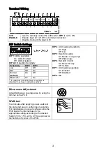
Terminal Wiring
LED
ENABLE
Used to remotely control the LEDs when
DIP1
is set to ON.
Enable: input is +12V OR no terminal connection
Disable: Connect the input to 0V
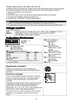
DIP Switch Settings
DIP 1
: LEDs operation
On: LEDs Enabled
Off: LEDs Disabled
DIP 2-3
: Detection Sensitivity
Sensitivity
DIP2
DIP3
Low Off
Off
Mid Off
On
Normal
(
Default
)
On Off
Maximum* On
On
* In maximum sensitivity sway recognition is
disabled to achieve maximum sensitivity
DIP 4
: Anti masking Sensitivity
On: High
Off: Low
DIP 5
: Detector's optics
On: Barrier / Long range
Off: Wide angle
DIP 6
: Red LED /3 LED
On: Red LED only
Off: 3 LEDs
DIP 7
: Anti masking operation
On: Enabled
Off: Disabled
DIP 8
: N/A
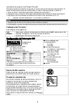
Microwave Adjustment
Adjust Microwave coverage area by using the
trimmer on the PCB.
MIN
MAX
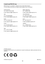
Walk test
Two minutes after applying power, walk test
the protected area to verify proper operation.
For installations on uneven surfaces slide the
PCB inside the internal base to the
appropriate setting according to the desired
height (1.0m, 1.5m, 2.2m, 2.7m) as printed on
the bottom left corner of the PCB.
1.00M
1.50M
2.20M
2.70M
PCB


