background image

12

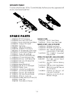
SEPARATE FRAME

To remove the Camera, VTX or Control Module, the frame must be separated. All 
4 arms must be removed first.

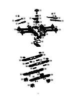
SPARE PARTS

  1  RISE2020  FPV VTX Antenna
  2  RISE2009  Prop Nuts CW/CCW
  3  RISE2010  Props CW/CCW 2 Yel/2 Black
  4  RISE2019  Camera VTX CASE
  5  RISE2001  Top Cover
  6  RISE2017  25mW VTX Camera
  6  RISE2018  200mW VTX Camera
  7  RISE2007  FC Board Module w/Arm Sockets
  8  RISE2025  Control Board Dampers (4)
  9  RISE2015  Frame Left and Right
10  RISE2006  L/R Arm CCW Motor ESC
11  RISE2004  L/F Arm CW Motor ESC
12  RISE2003  R/F Arm CCW Motor ESC
13  RISE2005  R/R Arm CW Motor ESC
14 RISE2000 Canopy
15  RISE2026  Motor Shields (4)
16  RISE2022  LiPo 3S 11.1V 1500mAH
17 RISE2002 Battery Cover
18  RISE2013  L/R Arm Top and Bottom
19  RISE2011  L/F Arm Top and Bottom
20  RISE2012  R/F Arm Top and Bottom
21  RISE2014  R/R Arm Top and Bottom
22  RISE2016  LED Arm Covers (4)
23 RISE2008 Landing Gear (4) w/Screws (12)
 RISE2021 

Screw 

Set

 RISJ2000 

Transmitter 

6-Channel

GOGGLES PARTS

  TACZ5610  FPV-G1 Head Strap
  TACZ5612  FPV-G1 Face Plate Foam

MONITOR PARTS AND ACCESSORIES

  TACZ5600  FPV-RM2 Sun Shield
  TACZ5602  FPV-RM2 Tripod Mount
 TACZ5300  

FPV 5.8GHz RP-SMA TX 
Antenna Short 110mm 3dBi

 TACZ5305  

FPV 5.8GHZ Cloverleaf 
Antenna 3dBi

OTHER OPTIONAL PARTS AND ACCESSORIES

 RISE2509   

RX Flight control board 
extension cable

 TACZ1010  

4G Class 10 Micro Memory 
Card

  TACZ5604  USB Micro SD Card Reader
 TACL0625  

TR625 6-Channel SLT Receiver 
Twin Antennas

 TACJ2650  

TTX650 6 - Channel SLT 
Computer Transmitter

 DTXP4620  

Duratrax Li-24 2S-4S AC 
Balance Charger

Summary of Contents for FPV RACER

Page 1: ...or the safe operation of the product Before use if you feel that this product is not for you please return it to the place of purchase Manual Specifications and Description Changes The instruction manual warranties and other associated documentation are subject to change without notice Hobbico assumes no responsibility for inadvertent errors to this manual ...

Page 2: ...rs The spinning blades of a model quadcopter can cause serious injury When choosing a flying site for your VUSION FPV RACER stay clear of buildings trees and power lines AVOID flying in or near crowded areas DO NOT fly close to people or pets Maintain a safe distance from the quadcopter Your VUSION FPV RACER should not be considered a toy Because of its performance capabilities the VUSION FPV RACE...

Page 3: ...l scale aircraft and avoid flying near or over groups of people BATTERY WARNINGS ALWAYS unplug your battery from either the charger or quadcopter after use NEVER store your quadcopter with the battery plugged into the quadcopter DO NOT attempt to charge your battery if it becomes swollen or hot The VUSION FPV RACER does not have a voltage cutoff failsafe When the alarm sounds land the quad and dis...

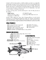
Page 4: ...me return shipping address as much contact information as possible daytime telephone number fax number e mail address a detailed description of the problem and a photocopy of the purchase receipt Upon receipt of the package the problem will be evaluated as quickly as possible FEATURES Entry Level 250 class racing quad Oneshot125 speed controls 2280kV 1806 size Brushless motors Ready to Fly no buil...

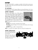
Page 5: ... the 3S port on the charger When charging the charge status LED will illuminate solid RED When charge is complete the LED will change to solid GREEN Typical charge time of a depleted battery is approximately 2 hours NOTE A blinking red charge status LED indicates a charging error NEVER leave the battery unattended while charging ALWAYS unplug the charger from the outlet and the battery when chargi...

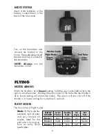
Page 6: ...o the right to arm the motors Holding the yaw control to the left while the throttle is at its lowest setting will disarm the motors The motors will also shut off if the throttle is its lowest setting for more than 3 seconds FLIGHT MODES The Vusion has 3 flight modes Mode 1 This mode has autolevel mild roll rates and very limited tilt angles Ideal for the pilot who is moving up from an entry level...

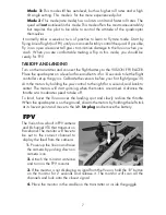
Page 7: ...ight controller set up the gyros Calibrate the sensors before your first flight page 10 Arm the motors by holding the yaw control to the right for a second and back to center The motors will start spinning when the motors are armed Advance the throttle at a moderate speed to take off To land hover the Vusion over the landing spot and slowly reduce the throttle When the quadcopter is on the ground ...

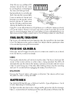
Page 8: ...uadcopter when it has crashed by turning off the transmitter VUSION CAMERA Video clips and still images from the Vusion s camera can saved to an on board micro SD memory card not included VIDEO Pressing the video button will start and stop the video The timer in the lower left corner of the monitor will be on while video is being recorded The DVR will automatically save the video to the memory car...

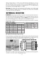
Page 9: ...l set up using the following chart as a guide CHANNEL ASSIGNMENTS MODEL TYPE Airplane NOTE Spektrum JR systems should have opposite directions Channel Aileron Elevator Throttle Rudder Gear AUX Direction normal reverse reverse reverse normal reverse Dual Rates 80 100 80 100 80 100 Expo 20 0 20 0 20 0 End Points 100 100 100 100 100 100 100 100 100 100 100 100 SWITCH ASSIGNMENTS Ch 5 AUX AUX AUX 100 ...

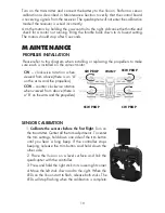
Page 10: ... motor CW clockwise rotation when viewed from above there is an A on the arms and the propellers CCW counter clockwise rotation when viewed from above there is a B on the arms and the propellers SENSOR CALIBRATION 1 Calibrate the sensors before the first flight Turn on the transmitter Center all the trim adjustments To center the trim settings hold down one side of the trim button until you hear a...

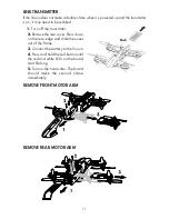
Page 11: ... transmitter 2 Remove the rear cover Press down on the rear edge and slide the cover out of the frame 3 Connect the battery to the Vusion 4 Press and hold the red button until the red and white LEDs on the board start flashing 5 Turn on the transmitter The board should make the second chime immediately REMOVE FRONT MOTOR ARM REMOVE REAR MOTOR ARM Push ...

Page 12: ...17 RISE2002 Battery Cover 18 RISE2013 L R Arm Top and Bottom 19 RISE2011 L F Arm Top and Bottom 20 RISE2012 R F Arm Top and Bottom 21 RISE2014 R R Arm Top and Bottom 22 RISE2016 LED Arm Covers 4 23 RISE2008 Landing Gear 4 w Screws 12 RISE2021 Screw Set RISJ2000 Transmitter 6 Channel GOGGLES PARTS TACZ5610 FPV G1 Head Strap TACZ5612 FPV G1 Face Plate Foam MONITOR PARTS AND ACCESSORIES TACZ5600 FPV ...

Page 13: ...13 ...

Page 14: ...Never disassemble or modify pack wiring in any way or puncture cells Never charge inside a vehicle Always disconnect the battery and unplug the charger when not in use Land your model immediately when the LEDs flash to indicate that the battery power is low Recharge the battery before attempting another flight A dangerous situation can occur when attempting to recharge an over discharged battery A...

Page 15: ...tested and found to comply with the limits for a Class B digital device pursuant to part 15 of the FCC Rules These limits are designed to provide reasonable protection against harmful interference in a residential installation This equipment generates uses and can radiate radio frequency energy and if not installed and used in accordance with the instructions may cause harmful interference to radi...

Page 16: ...CONFORMITY Product RISE 2 4GHz 6 Channel Tx Rx Item number RISJ2000 J2000 Equipment class 1 J2000 transmitter The objects of the declaration described here are in conformity with the requirements of the specifications listed below following the provisions of the European 2006 95 EC Low Voltage Directive EN 60950 1 2013 Safety The objects of the declaration described here are in conformity with the...

Reviews: